<?xml version="1.0" encoding="utf-8"?><feed xmlns="http://www.w3.org/2005/Atom" ><generator uri="https://jekyllrb.com/" version="4.4.1">Jekyll</generator><link href="https://shentian.me/feed.xml" rel="self" type="application/atom+xml" /><link href="https://shentian.me/" rel="alternate" type="text/html" /><updated>2026-04-01T20:04:26+00:00</updated><id>https://shentian.me/feed.xml</id><title type="html">Shen’s tech blog</title><subtitle>Tinkerer, Capetownian, Runner, Burner
</subtitle><author><name>Shen Tian</name></author><entry><title type="html">Building a Fadecandy in 2025: Part 2</title><link href="https://shentian.me/2025/07/06/build-fadecandy-2025-pt2.html" rel="alternate" type="text/html" title="Building a Fadecandy in 2025: Part 2" /><published>2025-07-06T00:00:00+00:00</published><updated>2025-07-06T00:00:00+00:00</updated><id>https://shentian.me/2025/07/06/build-fadecandy-2025-pt2</id><content type="html" xml:base="https://shentian.me/2025/07/06/build-fadecandy-2025-pt2.html"><![CDATA[<p>Well it’s been a while… let me say I got distracted from this project for a while. In the 18 months since <a href="/2023/12/28/build-fadecandy-2023-pt1.html">Part 1</a>, AI has made the job a lot easier than it would have been otherwise, but all commands were human verified – or at least, it worked on at least <del>one</del> two of my computers.</p>

<blockquote>
  <p>In Part 1, I documented the process of manufacturing my own Fadecandy boards, including converting design files from Eagle to KiCad, creating a BOM (filling in some missing details), and building a few boards.</p>
</blockquote>

<h1 id="overview">Overview</h1>

<p>In this part, I’ll flash the Fadecandy firmware onto the new boards we made in Part 1, using a SWD programmer and a custom jig. This will be followed by how to building the host software (<code class="language-plaintext highlighter-rouge">fcserver</code>), and how to build the firmware from source, and flashing it via USB.</p>

<p>Everything was tested on both Intel (macOS 11) and Apple-Silicone Mac (macOS 15). My fork of the <code class="language-plaintext highlighter-rouge">fadecandy</code> repo is <a href="https://github.com/shen-tian/fadecandy">here</a>.</p>

<h1 id="writing-to-a-blank-board">Writing to a blank board</h1>

<p>The ability to flash firmware via USB is a standard part of the Arduino developer experience. For this to work, a small program called a bootloader need to be present on the MCU. This is either flashed at the factory, or built in at a silicon level (e.g. RP2040). The MK20DX128, fresh from the factory has neither, so we’ll need to go a different route - JTAG/SWD, a low level protocol that allows direct write to MCU flash.</p>

<p>We need some extra hardware to do this. I’m going to use a <a href="https://www.segger.com/products/debug-probes/j-link/models/j-link-edu-mini/">Segger J-Link EDU Mini</a> programmer. There are several versions of this - though I believe the main difference is the type of USB connector. This has a standard ARM 10-pin JTAG connector. I’ve used an <a href="https://www.adafruit.com/product/2743">adapter</a> to break it out to 0.1” pins, to facilitate connecting it to the Fadecandy’s programming ports (a.k.a. its hacker port)</p>

<blockquote>
  <p>The Teensy 3, on which the device is based on uses a second, auxiliary MCU to handle the USB programming. This second MCU, with it’s proprietary firmware, is the magic sauce that makes a board a Teensy.</p>
</blockquote>

<h2 id="hacker-port">hacker port</h2>

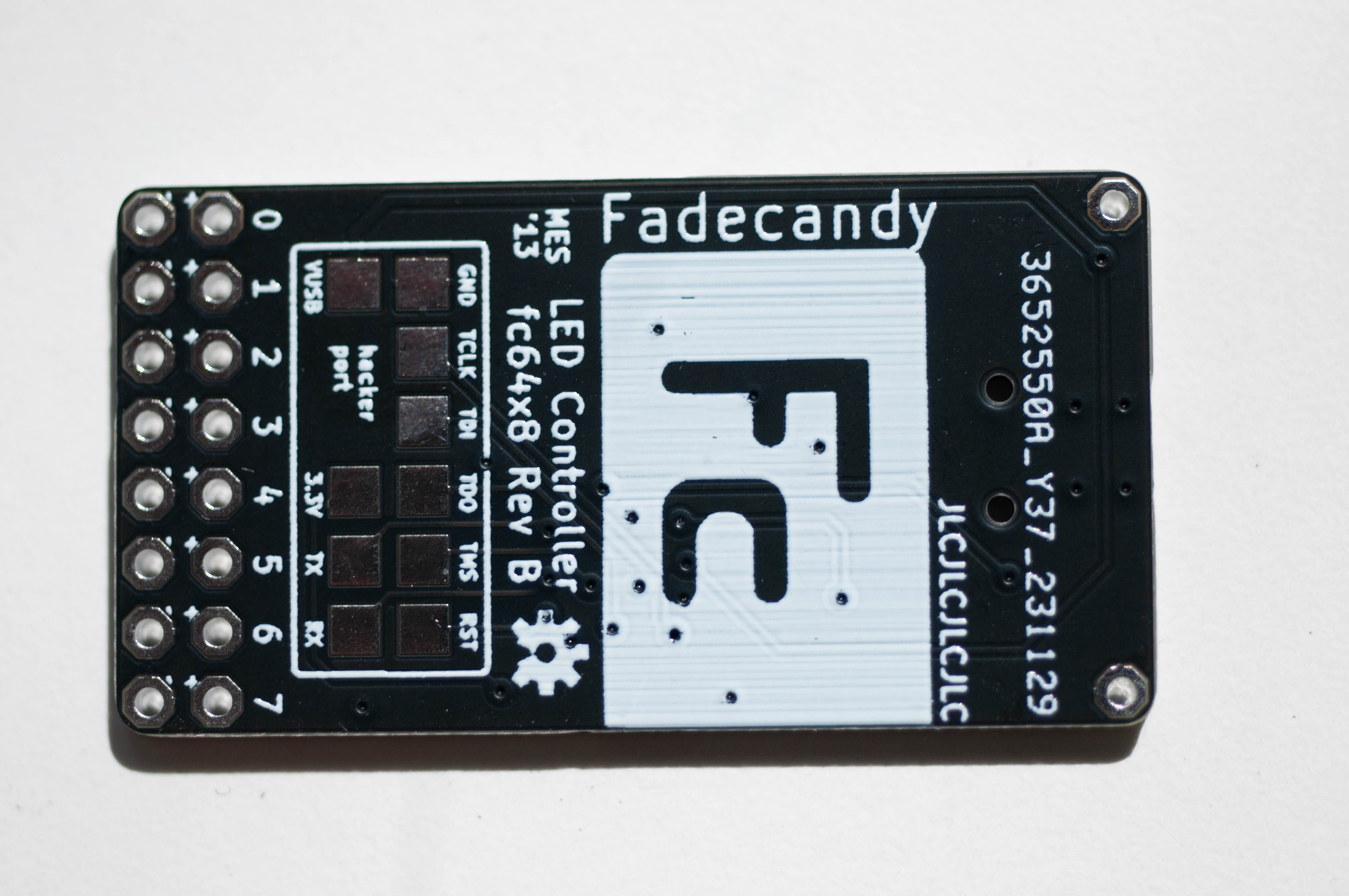
<p>The hacker port is a set of pads on the back side of the board. I’ve used a 0.1” pitch 2x6 pin pogo connector to make contact. The pins are unnumbered. Each contact is defined as its own test point in the PCB design file. For the sake of this post, I’ve numbered them as follows:</p>

<p>Here’s a pinout</p>

<p><a href="/assets/images/fc-hacker-port.jpg"><img src="/generated/fc-hacker-port-600-555e9d56e.jpg" alt="hacker port pin numbering" srcset="/generated/fc-hacker-port-600-555e9d56e.jpg 600w, /generated/fc-hacker-port-1200-555e9d56e.jpg 1200w" width="2622" height="1570"></a></p>

<table>
  <thead>
    <tr>
      <th>#</th>
      <th>Label</th>
      <th>Purpose</th>
    </tr>
  </thead>
  <tbody>
    <tr>
      <td>1</td>
      <td><strong>GND</strong></td>
      <td>Ground reference</td>
    </tr>
    <tr>
      <td>2</td>
      <td><strong>TCLK</strong></td>
      <td>JTAG clock/SWD CLK</td>
    </tr>
    <tr>
      <td>3</td>
      <td><strong>TDI</strong></td>
      <td>JTAG data-in (not used by SWD)</td>
    </tr>
    <tr>
      <td>4</td>
      <td><strong>TDO</strong></td>
      <td>JTAG data-out/SWD trace</td>
    </tr>
    <tr>
      <td>5</td>
      <td><strong>TMS</strong></td>
      <td>JTAG mode/SWD data</td>
    </tr>
    <tr>
      <td>6</td>
      <td><strong>RST</strong></td>
      <td>Active-low MCU reset</td>
    </tr>
    <tr>
      <td>7</td>
      <td><strong>VUSB</strong></td>
      <td>5V from USB jack</td>
    </tr>
    <tr>
      <td>8</td>
      <td> </td>
      <td>No connection</td>
    </tr>
    <tr>
      <td>9</td>
      <td> </td>
      <td>No connection</td>
    </tr>
    <tr>
      <td>10</td>
      <td><strong>3.3V</strong></td>
      <td>Regulated 3.3V</td>
    </tr>
    <tr>
      <td>11</td>
      <td><strong>TX</strong></td>
      <td>UART0 TX</td>
    </tr>
    <tr>
      <td>12</td>
      <td><strong>RX</strong></td>
      <td>UART0 RX</td>
    </tr>
  </tbody>
</table>

<p>Only five of these pins need to be connected to the JTAG connector for SWD</p>

<table>
  <thead>
    <tr>
      <th>J-Link 9-pin</th>
      <th>Fadecandy pad</th>
      <th>Comment</th>
    </tr>
  </thead>
  <tbody>
    <tr>
      <td>1 Vref</td>
      <td><strong>3.3V</strong></td>
      <td>Don’t feed power here – board must already be USB-powered</td>
    </tr>
    <tr>
      <td>2 SW(D)IO</td>
      <td><strong>TMS</strong></td>
      <td> </td>
    </tr>
    <tr>
      <td>4 CLK</td>
      <td><strong>TCLK</strong></td>
      <td> </td>
    </tr>
    <tr>
      <td>10 !RST</td>
      <td><strong>RST</strong></td>
      <td> </td>
    </tr>
    <tr>
      <td>3/5/9 GND</td>
      <td><strong>GND</strong></td>
      <td>at least one solid ground</td>
    </tr>
  </tbody>
</table>

<p>I built the following jig</p>

<p><a href="/assets/images/fadecandy/IMG_6005.jpg"><img src="/generated/fadecandy/IMG_6005-600-5769b5031.jpg" alt="board in jig" srcset="/generated/fadecandy/IMG_6005-600-5769b5031.jpg 600w, /generated/fadecandy/IMG_6005-1200-5769b5031.jpg 1200w" width="4032" height="3024"></a>
<a href="/assets/images/fadecandy/IMG_6006.jpg"><img src="/generated/fadecandy/IMG_6006-600-36f867d60.jpg" alt="just the jig" srcset="/generated/fadecandy/IMG_6006-600-36f867d60.jpg 600w, /generated/fadecandy/IMG_6006-1200-36f867d60.jpg 1200w" width="4032" height="3024"></a>
<a href="/assets/images/fadecandy/IMG_6008.jpg"><img src="/generated/fadecandy/IMG_6008-600-30558dc5a.jpg" alt="pogo closeup" srcset="/generated/fadecandy/IMG_6008-600-30558dc5a.jpg 600w, /generated/fadecandy/IMG_6008-1200-30558dc5a.jpg 1200w" width="4032" height="3024"></a>
<a href="/assets/images/fadecandy/IMG_6009.jpg"><img src="/generated/fadecandy/IMG_6009-600-766ef505d.jpg" alt="back of the jig" srcset="/generated/fadecandy/IMG_6009-600-766ef505d.jpg 600w, /generated/fadecandy/IMG_6009-1200-766ef505d.jpg 1200w" width="4032" height="3024"></a></p>

<blockquote>
  <p><a href="https://omnifixo.com/">It’s an Omnifixo</a> in case you are were wondering.</p>
</blockquote>

<p>Before flashing the bootloader, both the J-Link and Fadecandy need to be plugged into USB - the later just for power.</p>

<p>We’ll use OpenOCD to do the flashing. On macOS, run <code class="language-plaintext highlighter-rouge">brew install openocd</code> to install. We’ll want a config file to make this easier. Using <code class="language-plaintext highlighter-rouge">bootloader/openocd.cfg</code> as a starting point, we create the following config file:</p>

<p>content of <code class="language-plaintext highlighter-rouge">openocd_jlink.cfg</code></p>

<div class="language-plaintext highlighter-rouge"><div class="highlight"><pre class="highlight"><code># openocd_jlink.cfg  –  use with:  openocd -f openocd_jlink.cfg -c "program PATH_TO_HEX verify reset exit"

# 1. Interface: use SEGGER J-Link rather than the Olimex FTDI probe
source [find interface/jlink.cfg]

# 2. Tell the J-Link we’re speaking SWD, not JTAG
transport select swd

# 3. Keep the target definition (k40.cfg handles all K20/K40 variants)
set CHIPNAME mk20dx128        ;# or just 'k40' – pick one name
source [find target/k40.cfg]

# 4. SWD clock. 1 MHz is safe on a breadboard; faster once wiring is short
adapter speed 1000

# 5. Mass-erase &amp; program in one go
init; kinetis mdm halt; kinetis mdm mass_erase

</code></pre></div></div>

<p>A few things to note:</p>

<ul>
  <li>Lots of link rot in the original file! Thankfully, they all seem to refer to patches to OpenOCD to make it work with the chip. 12 years down the line, mainline OpenOCD seems to work fine. Thank you open source contributors!</li>
  <li>A few commands have changed - better defaults? support of the <code class="language-plaintext highlighter-rouge">kinetis mdm</code> commands?</li>
</ul>

<p>to flash it, run</p>

<div class="language-plaintext highlighter-rouge"><div class="highlight"><pre class="highlight"><code>openocd -f openocd_jlink.cfg -c "program ../bin/fc-firmware-v107.hex verify reset exit"
</code></pre></div></div>

<p>from the <code class="language-plaintext highlighter-rouge">bootloader</code> folder. This flashes the final factory firmware that Adafruit shipped (1.07).</p>

<p>You should see something like this:</p>

<div class="language-plaintext highlighter-rouge"><div class="highlight"><pre class="highlight"><code>Open On-Chip Debugger 0.12.0
Licensed under GNU GPL v2
For bug reports, read
	http://openocd.org/doc/doxygen/bugs.html
Info : add flash_bank kinetis k40.pflash
Info : J-Link EDU Mini V1 compiled Jun  6 2023 10:50:57
Info : Hardware version: 1.00
Info : VTarget = 3.277 V
Info : clock speed 1000 kHz
Info : SWD DPIDR 0x2ba01477
Info : [k40.cpu] Cortex-M4 r0p1 processor detected
Info : [k40.cpu] target has 6 breakpoints, 4 watchpoints
Info : MDM: Chip is unsecured. Continuing.
Info : starting gdb server for k40.cpu on 3333
Info : Listening on port 3333 for gdb connections
[k40.cpu] halted due to debug-request, current mode: Thread
xPSR: 0x01000000 pc: 0xfffffffe msp: 0xfffffffc
Info : MDM: Chip is unsecured. Continuing.
[k40.cpu] halted due to debug-request, current mode: Thread
xPSR: 0x01000000 pc: 0xfffffffe msp: 0xfffffffc
Info : Kinetis MK20DX128xxx5 detected: 2 flash blocks
Info : 1 PFlash banks: 128 KiB total
Info : 1 FlexNVM banks: 32 KiB total, 32 KiB available as data flash, 2048 bytes FlexRAM
Info : Disabling Kinetis watchdog (initial WDOG_STCTRLH = 0x01d3)
Info : WDOG_STCTRLH = 0x01d2
** Programming Started **
Info : Padding image section 0 at 0x00000ee4 with 284 bytes
Info : Flash protection requested in the programmed file differs from current setting.
Info : Data flash protection requested in the programmed file differs from current setting.
Info : Trying to re-program FCF.
** Programming Finished **
** Verify Started **
** Verified OK **
** Resetting Target **
Info : MDM: Chip is unsecured. Continuing.
shutdown command invoked
</code></pre></div></div>

<p>This should allow the board to enumerate on USB. To verify, run</p>

<div class="language-plaintext highlighter-rouge"><div class="highlight"><pre class="highlight"><code>system_profiler SPUSBDataType | grep -i -A3 -B3 "fadecandy"
</code></pre></div></div>

<p>we see</p>

<div class="language-plaintext highlighter-rouge"><div class="highlight"><pre class="highlight"><code>      Host Controller Driver: AppleT8132USBXHCI

        Fadecandy:

          Product ID: 0x607a
          Vendor ID: 0x1d50
</code></pre></div></div>

<p>That’s it! This should work like a Fadecandy from the shops! The binary included the custom (and DFU compatible) bootloader, so subsquent firmware updates can be via USB.</p>

<h1 id="host-software">Host software</h1>

<p>For a Fadecandy to work, we also need host software to connect to it over USB. <code class="language-plaintext highlighter-rouge">fcserver</code> is the provided and most commonly used one, as documented in the <a href="https://learn.adafruit.com/led-art-with-fadecandy">Adafruit guide</a>. The guide is very loud and clear that the code no longer works on 64 bit systems. A <a href="https://github.com/shen-tian/fadecandy/commit/91107391a89d17857f32b0b4c94a3b8a7f20f72d">trivial change</a> fixes this.</p>

<p>Of more significance, the soure made use of some git submodules which are no longer at their original location on github. I’ve included them in my fork.</p>

<p>A simple <code class="language-plaintext highlighter-rouge">make</code> should build <code class="language-plaintext highlighter-rouge">fcserver</code> now.</p>

<p><a href="https://docs.openlighting.org/ola/doc/latest/classola_1_1plugin_1_1usbdmx_1_1_scanlime_fadecandy.html">Open Lighting Architecture (OLA)</a> is actively maintained, and have built in Fadecandy support. I have not tested this.</p>

<h1 id="building-and-flashing-the-firmware">Building and flashing the firmware</h1>

<p>We can disconnect the J-Link and remove the Fadecandy from the jig, if you like. The rest will work over just USB.</p>

<p>First Install DFU-util and the compiler using <code class="language-plaintext highlighter-rouge">brew install arm-none-eabi-gcc dfu-util</code>. There’s been some changes in the build tools between 2013-2025. A <a href="https://github.com/shen-tian/fadecandy/commit/a71a81b7e233a990a6b85f4030d4ff19408e1c80">few small changes</a> (mostly to do with how standard lib is handled) was required before the firmware will build.</p>

<p>Run <code class="language-plaintext highlighter-rouge">make</code> from the firmware folder and confirm it actually built.</p>

<div class="language-plaintext highlighter-rouge"><div class="highlight"><pre class="highlight"><code>arm-none-eabi-gcc  -Wall -Wno-sign-compare -Wno-strict-aliasing -g -Os -mcpu=cortex-m4 -mthumb -nostdlib -MMD -Werror  -I.  -c -o usb_desc.o usb_desc.c
arm-none-eabi-gcc  -Wall -Wno-sign-compare -Wno-strict-aliasing -g -Os -mcpu=cortex-m4 -mthumb -nostdlib -MMD -Werror  -I.  -c -o usb_dev.o usb_dev.c
arm-none-eabi-gcc  -Wall -Wno-sign-compare -Wno-strict-aliasing -g -Os -mcpu=cortex-m4 -mthumb -nostdlib -MMD -Werror  -I.  -c -o usb_mem.o usb_mem.c
arm-none-eabi-g++ -std=gnu++0x -felide-constructors -fno-exceptions -fno-rtti -Wall -Wno-sign-compare -Wno-strict-aliasing -g -Os -mcpu=cortex-m4 -mthumb -nostdlib -MMD -Werror  -I.  -c -o fadecandy.o fadecandy.cpp
arm-none-eabi-g++ -std=gnu++0x -felide-constructors -fno-exceptions -fno-rtti -Wall -Wno-sign-compare -Wno-strict-aliasing -g -Os -mcpu=cortex-m4 -mthumb -nostdlib -MMD -Werror  -I.  -c -o fc_usb.o fc_usb.cpp
arm-none-eabi-gcc -Os -Wl,--gc-sections -mcpu=cortex-m4 -mthumb -nostdlib -Tfcb-app.ld -o fc-firmware.elf startup.o pins_teensy.o usb_desc.o usb_dev.o usb_mem.o serial1.o fadecandy.o fc_usb.o OctoWS2811z.o -lm -lc -lgcc -lnosys
arm-none-eabi-size fc-firmware.elf
   text	   data	    bss	    dec	    hex	filename
  16340	      0	  15651	  31991	   7cf7	fc-firmware.elf
arm-none-eabi-objcopy -O binary fc-firmware.elf fc-firmware.dfu
dfu-suffix -a fc-firmware.dfu
dfu-suffix (dfu-util) 0.11

Copyright 2011-2012 Stefan Schmidt, 2013-2020 Tormod Volden
This program is Free Software and has ABSOLUTELY NO WARRANTY
Please report bugs to http://sourceforge.net/p/dfu-util/tickets/

Suffix successfully added to file
arm-none-eabi-objcopy -O ihex fc-firmware.elf app-image.hex
(grep -v :00000001FF ../bin/fc-boot-v101.hex; cat app-image.hex) &gt; fc-firmware.hex
</code></pre></div></div>

<p><code class="language-plaintext highlighter-rouge">make install</code> should flash it onto the board via DFU:</p>

<div class="language-plaintext highlighter-rouge"><div class="highlight"><pre class="highlight"><code>dfu-util -d 1d50 -D fc-firmware.dfu
dfu-util 0.11

Copyright 2005-2009 Weston Schmidt, Harald Welte and OpenMoko Inc.
Copyright 2010-2021 Tormod Volden and Stefan Schmidt
This program is Free Software and has ABSOLUTELY NO WARRANTY
Please report bugs to http://sourceforge.net/p/dfu-util/tickets/

Opening DFU capable USB device...
Device ID 1d50:607a
Run-Time device DFU version 0101
Claiming USB DFU (Run-Time) Interface...
Setting Alternate Interface zero...
Determining device status...
DFU state(0) = appIDLE, status(0) = No error condition is present
Device really in Run-Time Mode, send DFU detach request...
Device will detach and reattach...
Opening DFU USB Device...
Claiming USB DFU Interface...
Setting Alternate Interface #0 ...
Determining device status...
DFU state(2) = dfuIDLE, status(0) = No error condition is present
DFU mode device DFU version 0101
Device returned transfer size 1024
Copying data from PC to DFU device
Download	[=========================] 100%        16340 bytes
Download done.
DFU state(7) = dfuMANIFEST, status(0) = No error condition is present
dfu-util: unable to read DFU status after completion (LIBUSB_ERROR_NO_DEVICE)
make: *** [install] Error 74
</code></pre></div></div>

<p>It might also be handy to flash one of the pre-compiled firmware binaries:</p>

<div class="language-plaintext highlighter-rouge"><div class="highlight"><pre class="highlight"><code>dfu-util -d 1d50 -D ../bin/fc-firmware-v107.dfu
</code></pre></div></div>]]></content><author><name>Shen Tian</name></author><summary type="html"><![CDATA[Well it’s been a while… let me say I got distracted from this project for a while. In the 18 months since Part 1, AI has made the job a lot easier than it would have been otherwise, but all commands were human verified – or at least, it worked on at least one two of my computers.]]></summary></entry><entry><title type="html">Building a Fadecandy in 2023: Part 1</title><link href="https://shentian.me/2023/12/28/build-fadecandy-2023-pt1.html" rel="alternate" type="text/html" title="Building a Fadecandy in 2023: Part 1" /><published>2023-12-28T00:00:00+00:00</published><updated>2023-12-28T00:00:00+00:00</updated><id>https://shentian.me/2023/12/28/build-fadecandy-2023-pt1</id><content type="html" xml:base="https://shentian.me/2023/12/28/build-fadecandy-2023-pt1.html"><![CDATA[<p>I’m doing some maintenance/planning for an existing project that makes use of over a dozen Fadecandy LED controllers. Given these have been out of production for a few years, why not take advantage of the fact that it’s open source, and make some myself?</p>

<blockquote>
  <p>The creator of Fadecandy, Micah Elizabeth Scott, aka scanlime, seems to have stepped away from the project. She has deleted much of the official content, including the github repo. As it happens, I’ve already started a lot of the planning work for these DIY Fadecandies, before the github repo was deleted. I debated a bit on whether it’s appropriate to do this write up, given that the project creator would rather not see it continue. In the end, I believe an aspect of open source is to decouple the creation from the creator. With that in mind, consider this a tribute to the project.</p>
</blockquote>

<h3 id="objective">Objective</h3>

<ul>
  <li>Document what it takes to build a Fadecandy board in 2023</li>
  <li>Provide information that might be useful for people maintaining existing projects: updated instructions on
    <ul>
      <li>How to build and flash the firmware</li>
      <li>How to build/run the host side software</li>
    </ul>
  </li>
  <li>Show the project some appreciation</li>
  <li>Learn a few things for myself, and hopefully help one or two other people learn a few things.</li>
</ul>

<h3 id="non-goals">Non-goals</h3>

<ul>
  <li>Any continuation/expansion/evolution of the project</li>
  <li>Producing more than a handful of new boards. Certainly nothing commercial</li>
  <li>Commitment to keeping any of the documentation up to date</li>
</ul>

<h2 id="bill-of-materials">Bill of Materials</h2>

<p>The goal is a reasonably close reproduction of an Adafruit revision B board. The Eagle files were in the repo, and I believe this makes up for the vast majority of Fadecandies made.</p>

<p>It’s worth noting that a Fadecandy, electrically, is based on a <a href="https://www.pjrc.com/store/teensy3.html">Teensy 3.0</a> + <a href="https://www.pjrc.com/store/octo28_adaptor.html">OctoWS2811 adapter</a>, less Teensy’s two-chip bootloader setup, plus a 5V power supply. This will be useful in most component selection questions. I made good use of <a href="https://forum.pjrc.com/index.php?threads/questions-on-teensy-3-1-components.26916/">this forum thread</a>.</p>

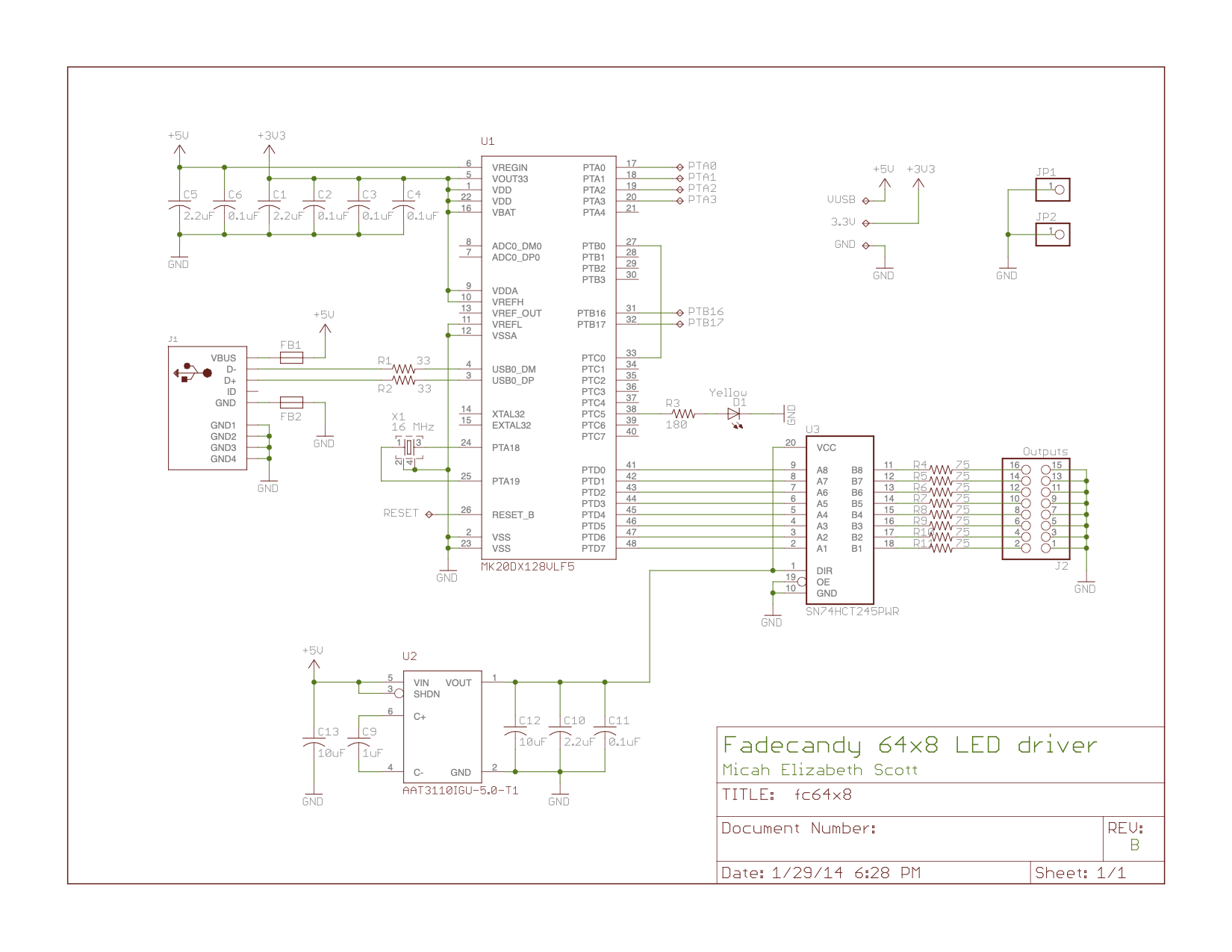
<p><a href="/assets/images/fc64x8-schematic.png"><img src="/generated/fc64x8-schematic-600-28c3e987b.jpg" alt="fx64x8 schematic" srcset="/generated/fc64x8-schematic-600-28c3e987b.jpg 600w, /generated/fc64x8-schematic-1200-28c3e987b.jpg 1200w" width="1650" height="1275"></a></p>

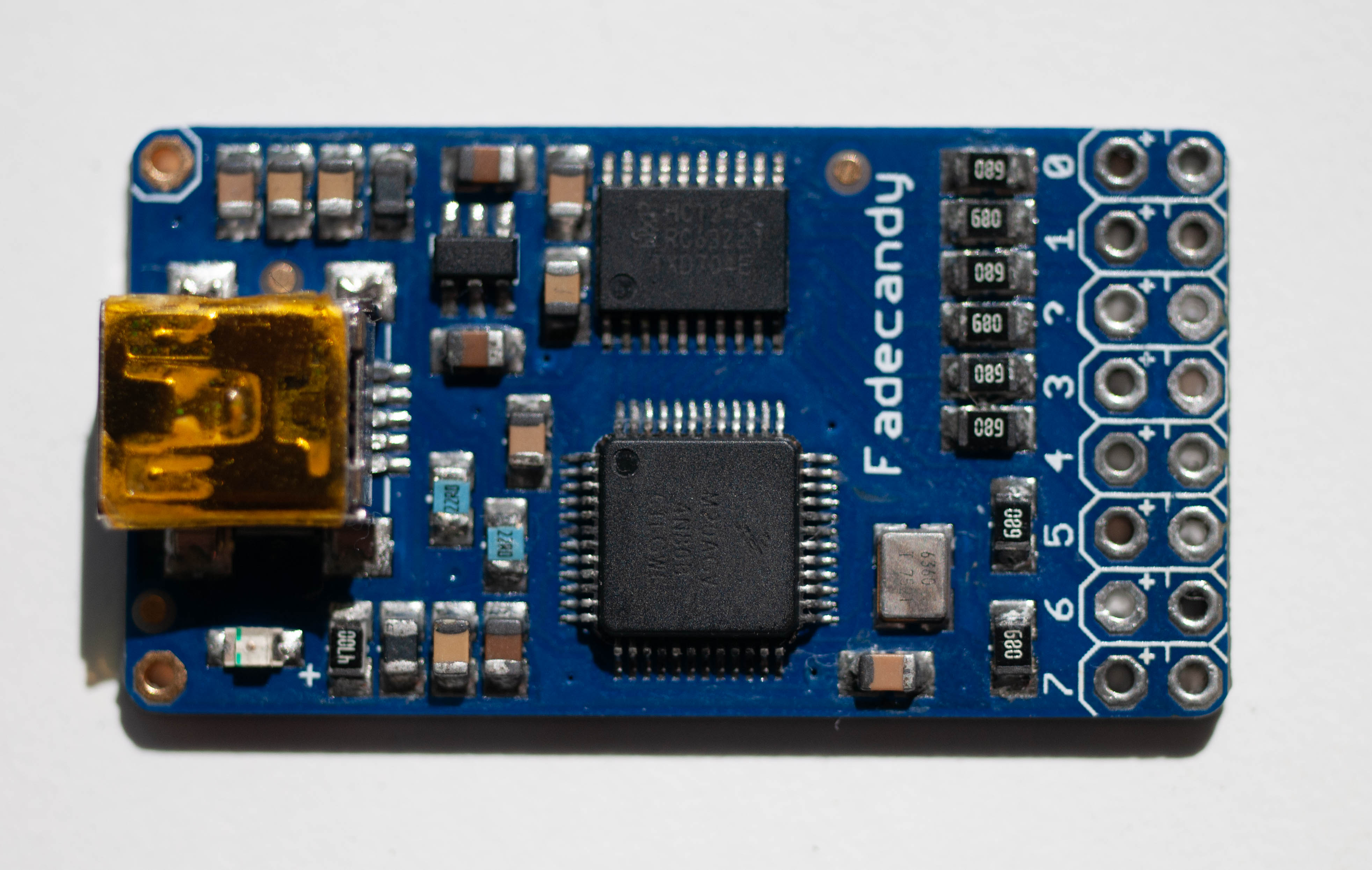
<p>A example of a (water damaged and dead) Fadecandy rev b board</p>

<p><a href="/assets/images/fadecandy/DSC_8498.jpg"><img src="/generated/fadecandy/DSC_8498-600-6b5df64e4.jpg" alt="rev b fadecandy" srcset="/generated/fadecandy/DSC_8498-600-6b5df64e4.jpg 600w, /generated/fadecandy/DSC_8498-1200-6b5df64e4.jpg 1200w" width="3927" height="2490"></a></p>

<p>Working through the schematic…</p>

<h3 id="microprocessor-and-its-crystal">Microprocessor and its crystal</h3>

<p>The core of the board is a NXP MK20DX128VLF5 - this microprocessor was originally released by Freescale in the early 2010s. It’s part of the Kinetis K20 family. It consists of a 50Mhz Cortex M4 core, 128KB of flash, and comes in a 48 pin LQFN package. As of late 2023, it’s still listed as “Active” by NXP. Stock availability is a bit patchy. I manage to buy a handful after looking across a few shops via <a href="https://octopart.com/search?q=MK20DX128VLF5&amp;currency=USD&amp;specs=0">Octopart</a>. I expect this will go obsolete at some stage, and it will become impossible to produce firmware compatible boards.</p>

<p>It uses a handful of MLCC capacitors for decoupling. I’m going with some X5R or X7R 0805 parts, rated at 16V or higher.</p>

<p>Selecting the crystal takes a little bit more research. It’s a 4-pin 3.2x2.5mm SMD part. The schematics label it at 16Mhz. We need to determine its accuracy, load capacitance, and ESR. Digging <a href="https://forum.pjrc.com/index.php?threads/questions-on-teensy-3-1-components.26916/">this</a> and <a href="https://forum.pjrc.com/index.php?threads/teensy-3-x-crystal.27378/">this</a> forum threads, we arrive at 10ppm or less stability, a bit less than 10pF or load capacitance. Looking at parts on Digikey that fits this description, we are looking at probably at least 50Ohm ESR.</p>

<p>I learnt about matching load capacitors to crystals in the <a href="https://datasheets.raspberrypi.com/rp2040/hardware-design-with-rp2040.pdf">RP2040 Hardware design guide</a>, so I was a bit surprised to see that that the schematic didn’t include any load capacitors. the second thread linked to above yielded the information that the K20 MCU has software configurable internal load capacitors. To find out what the Fadecandy uses, I searched the relevant register names in the repo, and found these lines in the bootloader code.</p>

<div class="language-plaintext highlighter-rouge"><div class="highlight"><pre class="highlight"><code>    // enable capacitors for crystal
    OSC0_CR = OSC_SC8P | OSC_SC2P;
</code></pre></div></div>

<p>i.e. 10pF load capacitor configured. If we assume 3pF for trace capacitance… that gives around 8pF for the crystal. This checks out with the “a bit less than 10pF” from above! (The RP2040 Hardware design guide has a good section on this calculation in page 9.)</p>

<p>With all the above information, I went with an Epson part rated at 9pF, 10ppm stability and 60Ohms ESR. As it happens, the RGB-123 PCB design files included a BOM, which specified a very similar part (slightly lower stability/tolerance).</p>

<h3 id="charge-pump">Charge pump</h3>
<p>The design takes account of the fact that VBUS is nominally 5V for USB, it could be a lot lower in practice, especially when long cables and self powered hubs are used.</p>

<p>It includes a Skyworks AAT3110IGU-5.0-T1 charge pump, 100mA @ 5V output. This is discontinued and unavailable as of 2023. However, this is a <a href="https://www.eevblog.com/forum/beginners/the-term-jelly-bean/">jellybean part</a>, and there are plenty of alternatives, though this might require different complementary passives.</p>

<p>I’ve replaced this with a MPS MP9361, 110mA @ 5V pump. This operates at 1.35Mhz, v.s. 750Khz of the Skyworks part. The only thing this will need to drive is the level shifter, which has a max supply draw in the region of 70mA (though I suspect it’s a lot lower in practice).</p>

<p>The reference design in <a href="https://www.monolithicpower.com/en/documentview/productdocument/index/version/2/document_type/Datasheet/lang/en/sku/MP9361DJ-LF-Z/document_id/1192/">the datasheet</a> specifies a 0.47uF capacitor for flying cap (C9 in the schematic). The equation for flying capacitor values does suggest that capacitance being inversely proportional to frequency, so this makes sense. The datasheet also had different values for input/output caps, but those don’t have to be as exact, so I’ll leave them as they are.</p>

<p>The fact that this IC comes in a T(hin)SOT-23-6 package, whereas the original is a regular (thick?) SOT-23 doesn’t matter, as it’s purely a height issue.</p>

<h3 id="level-shifter">Level shifter</h3>

<p>This is responsible for shifting the 3.3V logic from the MCU up to 5V expected by WS2811 controllers. The schematic specifies a Texas Instruments SN74HCT245PWR Octo bus transceiver. This is available in large numbers as of 2023. As a member of the 7400 family, it’s likely to be made for the foreseeable future. In fact, the boards made by Adafruit used Nexperia 74HCT245PW versions. I used that version, as I had those on hand.</p>

<h3 id="usb-connector">USB connector</h3>

<p>The board uses a mini-B USB connector. It’s a common SMD footprint. I used a EDAC part that matched the Adafruit boards.</p>

<p>The connector has Ferrite Beads on the VBUS and GND lines. Going through forums, Paul suggested 600Ohm @ 100Mhz parts.</p>

<h3 id="hacker-port">Hacker port</h3>

<p>Lastly, the bottom of the board has a programming/debug header, in the form of 10 square test pads in a 2x6 2.54mm pitch array. One could easily solder onto these… but I ordered a spring loaded connector that I’ll build into a jig.</p>

<h3 id="resistor-changes">Resistor changes</h3>

<p>A visual inspection of the Adafruit boards I have show 22Ohm resistors for R1 and R2 (USB D+/D-) instead of the 33Ohm components in the schematic. I have no idea why, and chances are, it’s not crucial. I’m going to err on what went onto the manufactured boards.</p>

<p>The current limiting resistor for the indicator LED is 470Ohm instead of 180Ohm. This might be related to the schematic specifying a yellow LED, whereas the boards are populated with a green one… though those two colours tend to have similar forward voltages (~2.1V), so it might just be there to make it a bit less bright. This is also unlikely to be critical. I ended up swapping the LED to a white one, and used a 220Ohm resistor.</p>

<p>Lastly, the Eagle files specified 68Ohm for R4-R11. This matches the boards I have. However, the PDF schematic used 75Ohm. I’ve gone with 68Ohms. These resistors are there to reduce ringing, as discussed <a href="https://forum.arduino.cc/t/arduino-ws2812b-data-pin-resistor/533031">here</a>. There is no <em>right</em> value, as it depends on what you are going to wire the board up to.</p>

<h3 id="modified-bill-of-materials">(Modified) Bill Of Materials</h3>

<p>This decisions described above. For the capacitors and resistors, I included a Digikey part number as an illustration of a suitable part, but anything in spec would have worked (probably).</p>

<table>
  <thead>
    <tr>
      <th>Ref</th>
      <th>Description</th>
      <th>Manufacturer</th>
      <th>Part number</th>
      <th>Digikey</th>
    </tr>
  </thead>
  <tbody>
    <tr>
      <td>C1, C5, C12, C13</td>
      <td>Cap Cer 10uF 16V X5R 0805</td>
      <td> </td>
      <td> </td>
      <td>1276-1096-1-ND</td>
    </tr>
    <tr>
      <td>C2-C4, C6, C11</td>
      <td>Cap Cer 0.1uF 50V X7R 0805</td>
      <td> </td>
      <td> </td>
      <td>1276-1003-1-ND</td>
    </tr>
    <tr>
      <td>C9</td>
      <td>Cap Cer 0.47uF 16V X7R 0805</td>
      <td> </td>
      <td> </td>
      <td>1276-6483-1-ND</td>
    </tr>
    <tr>
      <td>C10</td>
      <td>Cap Cer 2.2uF 16V X7R 0805</td>
      <td> </td>
      <td> </td>
      <td>1276-1162-1-ND</td>
    </tr>
    <tr>
      <td>D1</td>
      <td>White 0805</td>
      <td> </td>
      <td> </td>
      <td>3147-B1701TW–20P000314U1930CT-ND</td>
    </tr>
    <tr>
      <td>FB1, FB2</td>
      <td>600 Ohms @ 100 MHz, Signal Line Ferrite Bead 0805</td>
      <td>Bourns</td>
      <td>MH2029-601Y</td>
      <td>MH2029-601YCT-ND</td>
    </tr>
    <tr>
      <td>J1</td>
      <td>USB - mini B USB 2.0 Receptacle Connector 5 Position Surface Mount, Right Angle</td>
      <td>EDAC</td>
      <td>690-005-299-043</td>
      <td>151-1206-1-ND</td>
    </tr>
    <tr>
      <td>R1, R2</td>
      <td>Res SMD 22Ohm 5% 1/8W 0805</td>
      <td> </td>
      <td> </td>
      <td>311-22ARCT-ND</td>
    </tr>
    <tr>
      <td>R3</td>
      <td>Res SMD 220Ohm 5% 1/8W 0805</td>
      <td> </td>
      <td> </td>
      <td>13-RC0805JR-13220RLCT-ND</td>
    </tr>
    <tr>
      <td>R4-R11</td>
      <td>Res SMD 68Ohm 5% 1/8W 0805</td>
      <td> </td>
      <td> </td>
      <td>311-68ARCT-ND</td>
    </tr>
    <tr>
      <td>U1</td>
      <td>ARM® Cortex®-M4 Kinetis K20 Microcontroller IC 32-Bit Single-Core 50MHz 128KB (128K x 8) FLASH 48-LQFP (7x7)</td>
      <td>NXP</td>
      <td>MK20DX128VLF5</td>
      <td>MK20DX128VLF50-ND</td>
    </tr>
    <tr>
      <td>U2</td>
      <td>Charge Pump Switching Regulator IC Positive Fixed 5V 1 Output 110mA SOT-23-6 Thin, TSOT-23-6</td>
      <td>MPS</td>
      <td>MP9361DJ-LF-Z</td>
      <td>1589-1744-1-ND</td>
    </tr>
    <tr>
      <td>U3</td>
      <td>Transceiver, Non-Inverting 1 Element 8 Bit per Element 3-State Output 20-TSSOP</td>
      <td>Nexperia</td>
      <td>74HCT245PW,118</td>
      <td>1727-6353-1-ND</td>
    </tr>
    <tr>
      <td>X1</td>
      <td>16 MHz ±10ppm Crystal 9pF 60 Ohms 4-SMD, No Lead</td>
      <td>Epson</td>
      <td>TSX-3225 16.0000MF09Z-AC0</td>
      <td>SER4069CT-ND</td>
    </tr>
  </tbody>
</table>

<h3 id="my-impression-of-the-design">My impression of the design</h3>

<ul>
  <li>It uses a Mini USB type B plug, though by 2013, Micro USB was already dominant (USB type C was only 2 years away!). I believe this is done for mechanical robustness.</li>
  <li>0805 components: these are huge! Not sure why this was chosen, as Adafruit’s SMD lines could certainly have handled small components.</li>
  <li>The 68 Ohm resistors didn’t use a resistor array component.</li>
</ul>

<h2 id="manufacturing">Manufacturing</h2>

<blockquote>
  <p>(I’ve also converted the Eagle files to KiCad. The process was somewhat manual, but nothing especially interesting.)</p>
</blockquote>

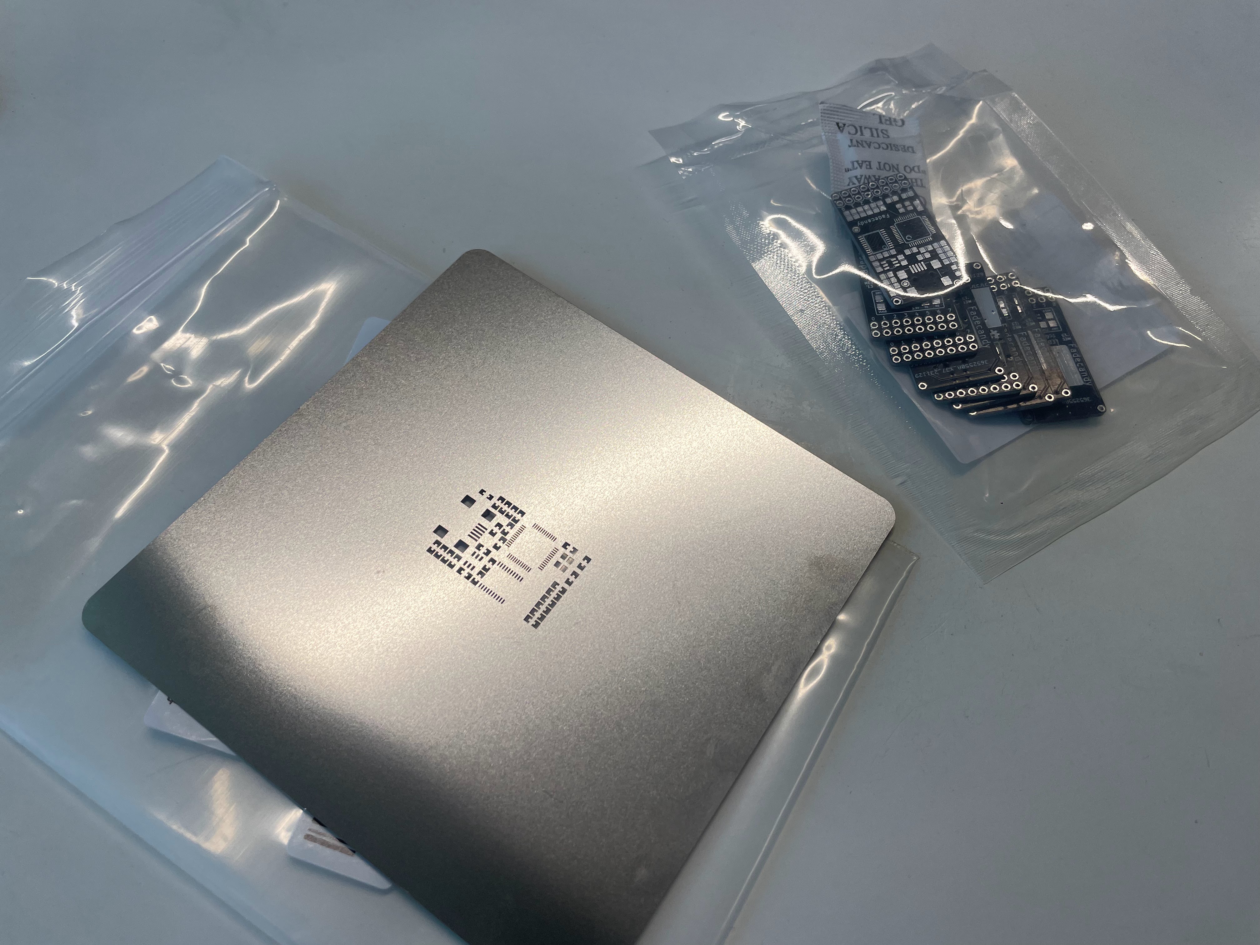
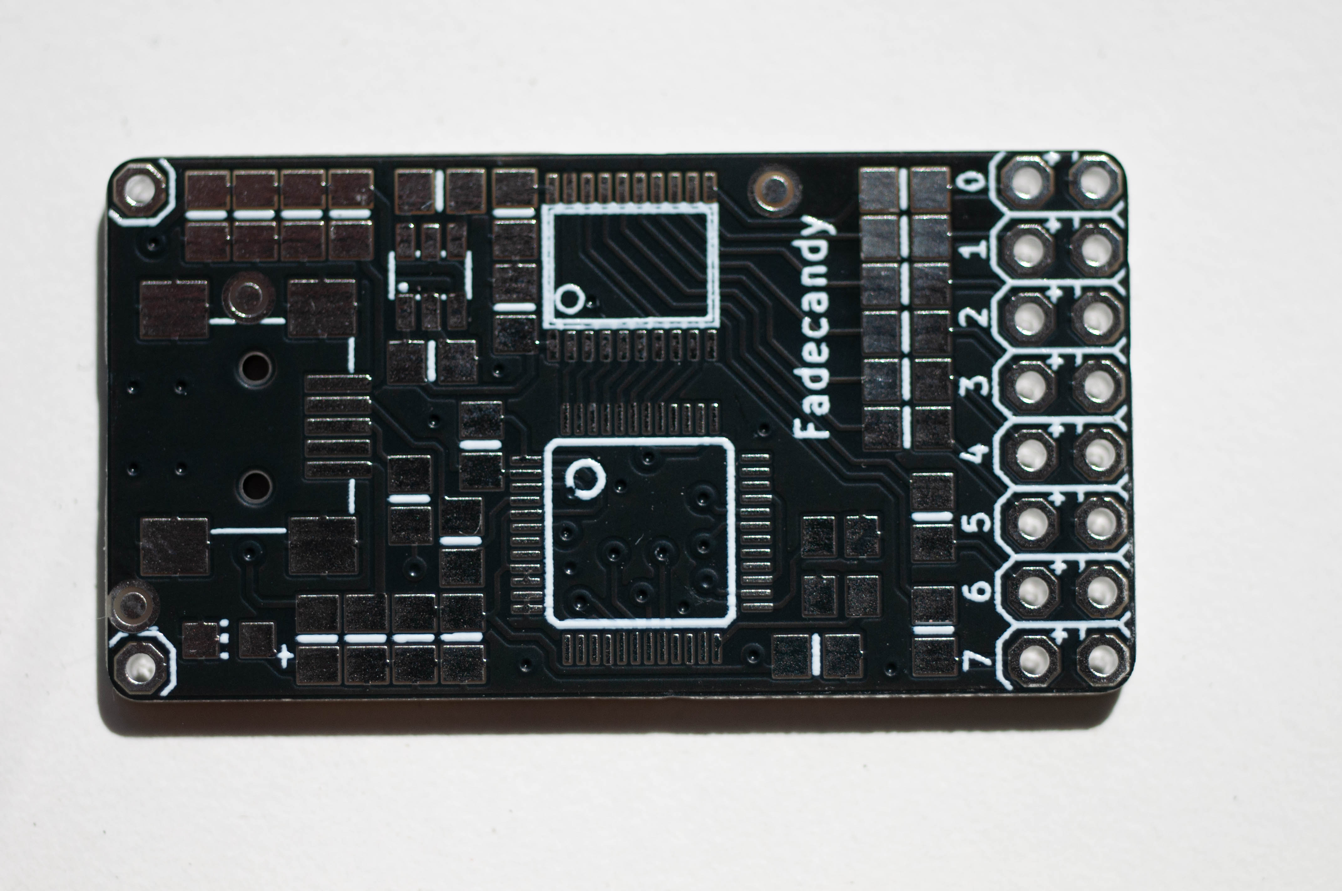
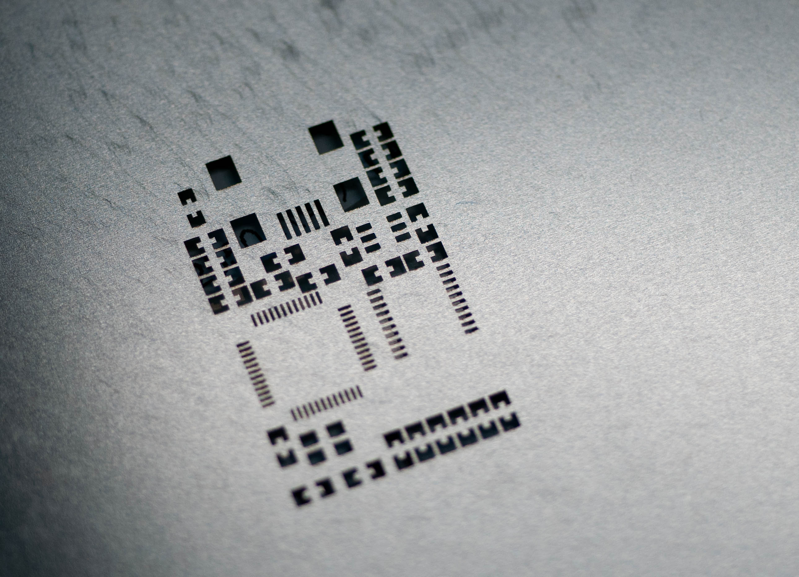
<p>I ordered the boards and a stencil from JLCPCB. It looks like hand soldering the board should be possible, but I didn’t try.</p>

<p><a href="/assets/images/fadecandy/IMG_1702.jpg"><img src="/generated/fadecandy/IMG_1702-600-b3a6a3f2b.jpg" alt="board and stencil" srcset="/generated/fadecandy/IMG_1702-600-b3a6a3f2b.jpg 600w, /generated/fadecandy/IMG_1702-1200-b3a6a3f2b.jpg 1200w" width="4032" height="3024"></a>
<a href="/assets/images/fadecandy/IMG_1701.jpg"><img src="/generated/fadecandy/IMG_1701-600-52a2ee2fa.jpg" alt="boards and stencils" srcset="/generated/fadecandy/IMG_1701-600-52a2ee2fa.jpg 600w, /generated/fadecandy/IMG_1701-1200-52a2ee2fa.jpg 1200w" width="4032" height="3024"></a>
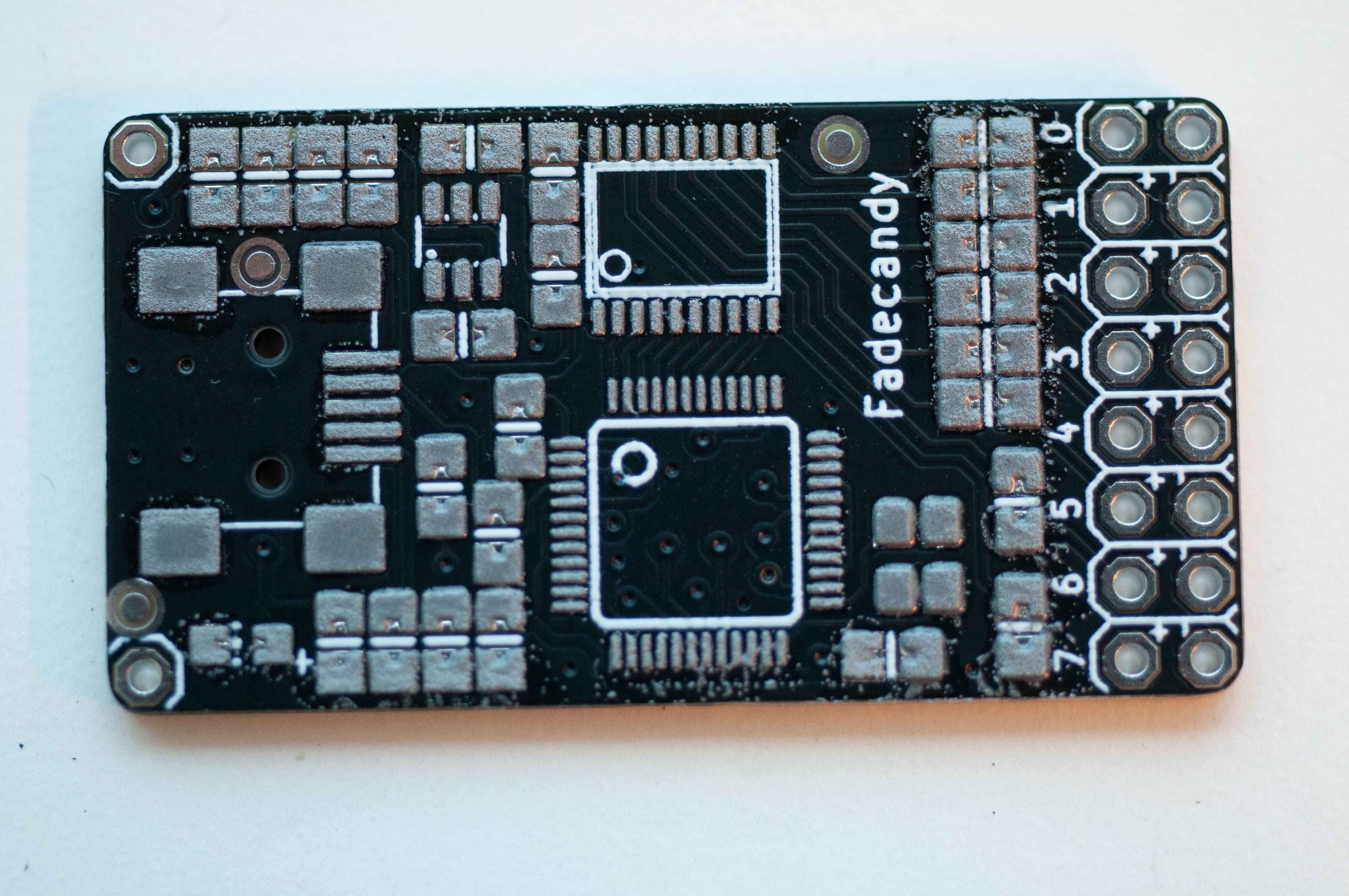
<a href="/assets/images/fadecandy/DSC_8500.jpg"><img src="/generated/fadecandy/DSC_8500-600-31d405ef6.jpg" alt="board front" srcset="/generated/fadecandy/DSC_8500-600-31d405ef6.jpg 600w, /generated/fadecandy/DSC_8500-1200-31d405ef6.jpg 1200w" width="4288" height="2848"></a>
<a href="/assets/images/fadecandy/DSC_8504.jpg"><img src="/generated/fadecandy/DSC_8504-600-28c7f992b.jpg" alt="board back" srcset="/generated/fadecandy/DSC_8504-600-28c7f992b.jpg 600w, /generated/fadecandy/DSC_8504-1200-28c7f992b.jpg 1200w" width="4288" height="2848"></a>
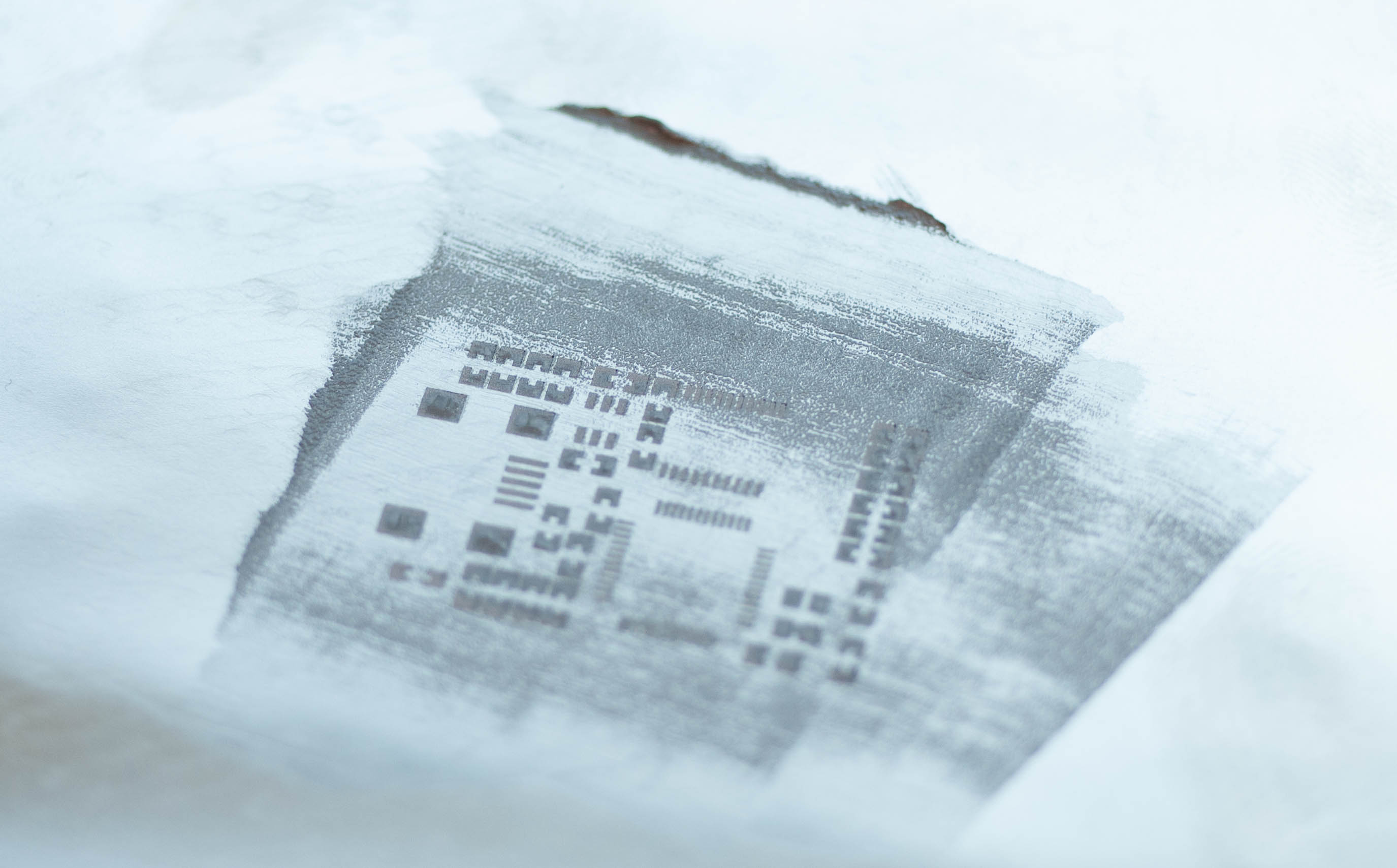
<a href="/assets/images/fadecandy/DSC_8517.jpg"><img src="/generated/fadecandy/DSC_8517-600-c619f7af2.jpg" alt="stencil closeup" srcset="/generated/fadecandy/DSC_8517-600-c619f7af2.jpg 600w, /generated/fadecandy/DSC_8517-1200-c619f7af2.jpg 1200w" width="2580" height="1862"></a></p>

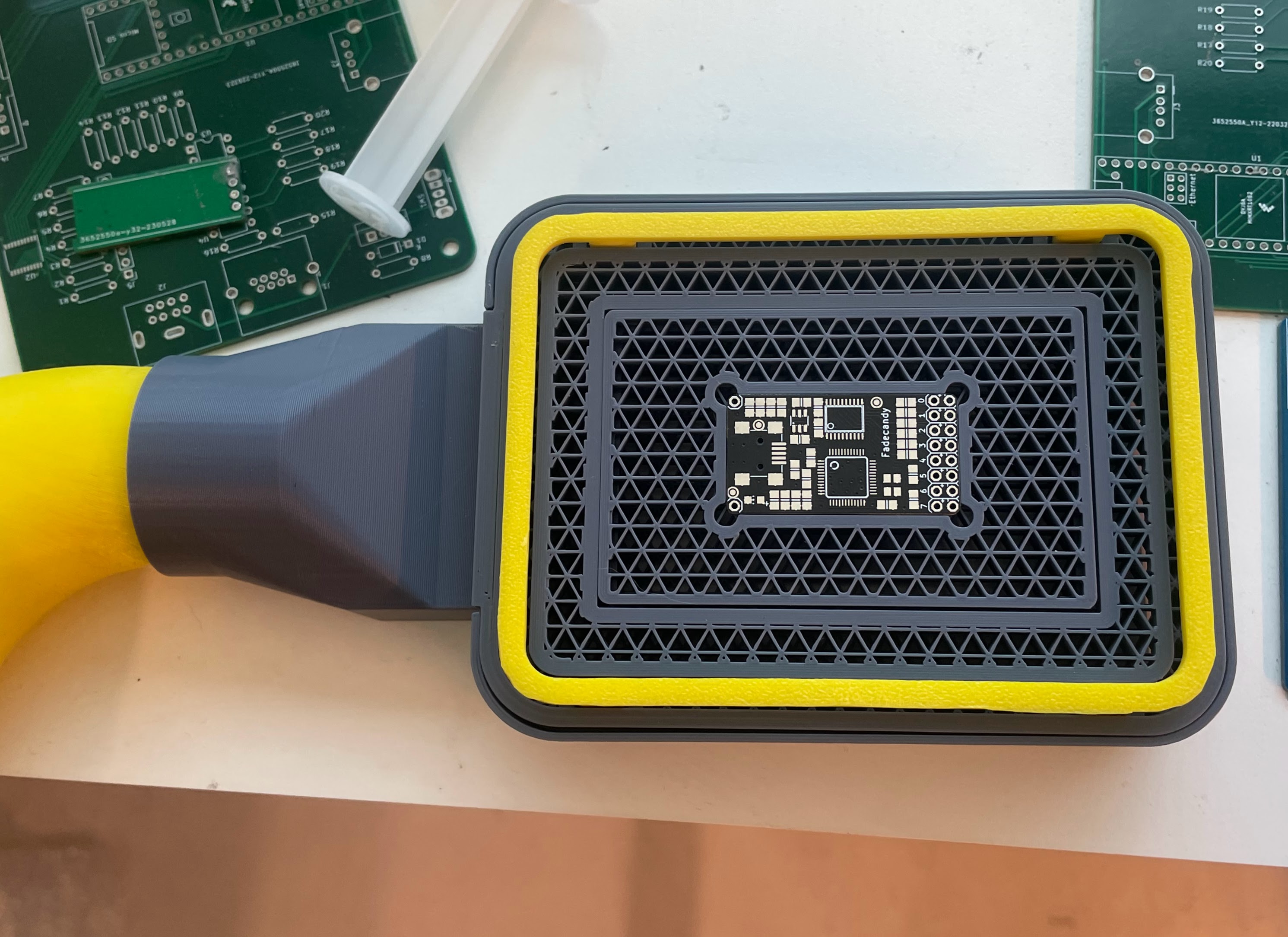
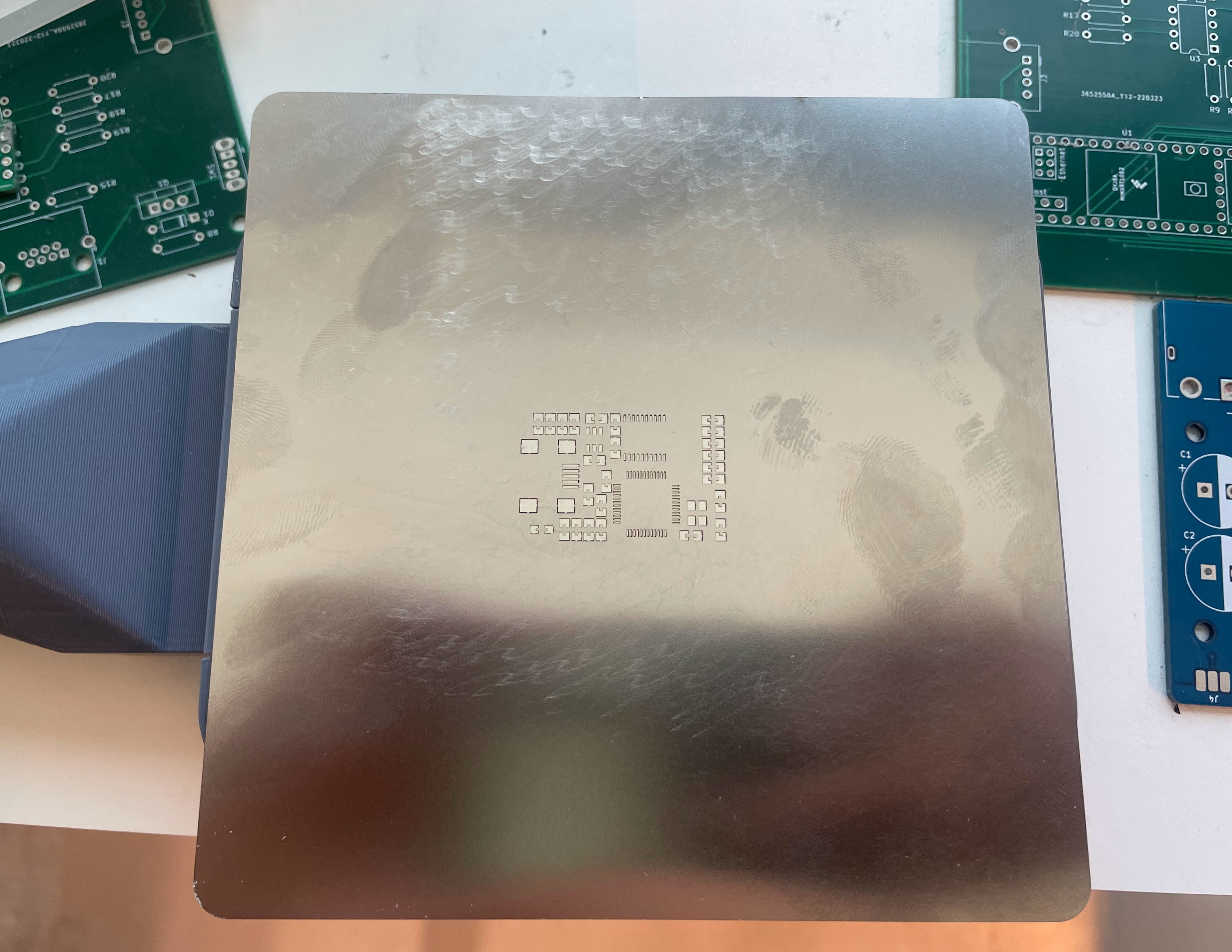
<p>I applied the paste using a <a href="https://www.youtube.com/watch?v=mEEo1tJj9D8&amp;ab_channel=MariusHeier">vacuum rig</a> to hold the stencil flat. It wasn’t as neat as it should have been. I’m still figuring out the vacuum method.</p>

<p><a href="/assets/images/fadecandy/IMG_1704.jpg"><img src="/generated/fadecandy/IMG_1704-600-58854dc28.jpg" alt="board in jig" srcset="/generated/fadecandy/IMG_1704-600-58854dc28.jpg 600w, /generated/fadecandy/IMG_1704-1200-58854dc28.jpg 1200w" width="2982" height="2168"></a>
<a href="/assets/images/fadecandy/IMG_1705.jpg"><img src="/generated/fadecandy/IMG_1705-600-fe80f10d9.jpg" alt="stencil aligned on jig" srcset="/generated/fadecandy/IMG_1705-600-fe80f10d9.jpg 600w, /generated/fadecandy/IMG_1705-1200-fe80f10d9.jpg 1200w" width="3607" height="2787"></a>
<a href="/assets/images/fadecandy/DSC_8526.jpg"><img src="/generated/fadecandy/DSC_8526-600-4111e7373.jpg" alt="paste applied" srcset="/generated/fadecandy/DSC_8526-600-4111e7373.jpg 600w, /generated/fadecandy/DSC_8526-1200-4111e7373.jpg 1200w" width="2750" height="1708"></a>
<a href="/assets/images/fadecandy/DSC_8533.jpg"><img src="/generated/fadecandy/DSC_8533-600-7a7cda508.jpg" alt="pasted board" srcset="/generated/fadecandy/DSC_8533-600-7a7cda508.jpg 600w, /generated/fadecandy/DSC_8533-1200-7a7cda508.jpg 1200w" width="4288" height="2848"></a>
<a href="/assets/images/fadecandy/DSC_8541.jpg"><img src="/generated/fadecandy/DSC_8541-600-ab81f905f.jpg" alt="boards with components" srcset="/generated/fadecandy/DSC_8541-600-ab81f905f.jpg 600w, /generated/fadecandy/DSC_8541-1200-ab81f905f.jpg 1200w" width="4288" height="2848"></a></p>

<p>This was all reflowed on an Aliexpress 100x100mm hot plate.</p>

<p><a href="/assets/images/fadecandy/DSC_8546.jpg"><img src="/generated/fadecandy/DSC_8546-600-ad2c683d3.jpg" alt="boards on hotplate" srcset="/generated/fadecandy/DSC_8546-600-ad2c683d3.jpg 600w, /generated/fadecandy/DSC_8546-1200-ad2c683d3.jpg 1200w" width="3543" height="2304"></a></p>

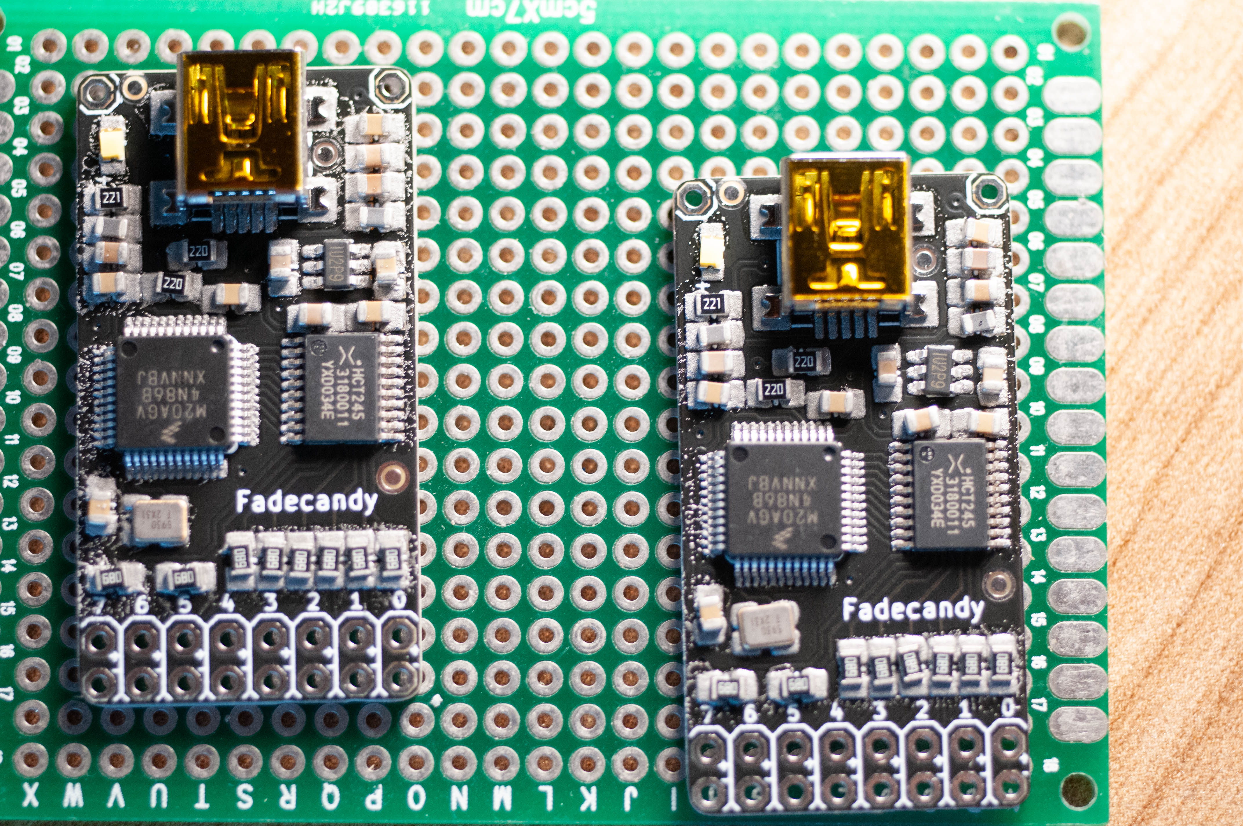
<p>There was some reworking needed to remove a few bridges around the LQFP package.</p>

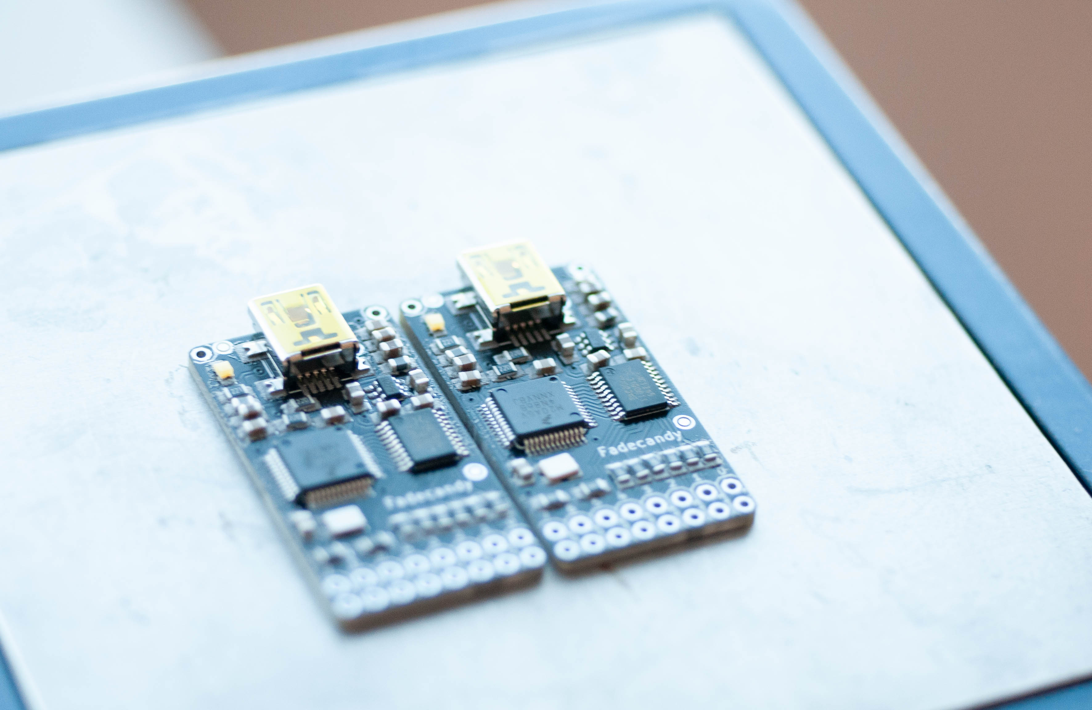
<p><a href="/assets/images/fadecandy/DSC_8548.jpg"><img src="/generated/fadecandy/DSC_8548-600-bf154bf95.jpg" alt="boards reflowed" srcset="/generated/fadecandy/DSC_8548-600-bf154bf95.jpg 600w, /generated/fadecandy/DSC_8548-1200-bf154bf95.jpg 1200w" width="4288" height="2848"></a></p>

<p>Next part: <a href="/2025/07/06/build-fadecandy-2025-pt2.html"><strong>programming!</strong></a></p>]]></content><author><name>Shen Tian</name></author><summary type="html"><![CDATA[I’m doing some maintenance/planning for an existing project that makes use of over a dozen Fadecandy LED controllers. Given these have been out of production for a few years, why not take advantage of the fact that it’s open source, and make some myself?]]></summary></entry><entry><title type="html">SiLabs CP2014 under macOS 10.13 High Sierra</title><link href="https://shentian.me/2018/05/14/cp2104-high-sierra.html" rel="alternate" type="text/html" title="SiLabs CP2014 under macOS 10.13 High Sierra" /><published>2018-05-14T00:00:00+00:00</published><updated>2018-05-14T00:00:00+00:00</updated><id>https://shentian.me/2018/05/14/cp2104-high-sierra</id><content type="html" xml:base="https://shentian.me/2018/05/14/cp2104-high-sierra.html"><![CDATA[<p>I recently wasted a few hours getting this to work. So documenting.</p>

<h2 id="problem">Problem</h2>

<p>Getting an <a href="https://learn.adafruit.com/adafruit-metro-mini/overview">Adafruit Metro Mini</a> recognised on a fresh-ish macOS install. The current revision of the board uses the SiLabs CP2104 chip, which requires a driver under macOS. I believe this chip is also used in a few other popular devboards. This is documented on Adafruit’s site (above link). However, this was broken for a few reasons. Net result is that though the driver appear to install correctly, plugging in the chip does not yield a serial port <code class="language-plaintext highlighter-rouge">cu.SLAB_USBtoUART</code>.</p>

<p>There’s a couple of posts/forum threads about it, but none, by themselves, helped me resolve this.</p>

<h2 id="the-causes">The causes</h2>

<p>As usual with these things, a bunch of things conspired to make this difficult. The two main drivers:</p>

<ul>
  <li>v5 of SiLabs’ CP210x USB to <a href="https://www.silabs.com/products/development-tools/software/usb-to-uart-bridge-vcp-drivers">UART driver</a> is/was <a href="https://www.silabs.com/community/interface/forum.topic.html/cp120x_vcp_driverno-G1Bu">incorrectly signed</a>. This might have been fixed now, but I used the v4 driver (labeled Legacy MacVCP Driver) in the download.</li>
  <li>In macOS 10.13, Apple changed some security stuff around System Extension things, detailed <a href="https://developer.apple.com/library/content/technotes/tn2459/_index.html">here</a>. This only affects new extensions. Ones already installed are grandfather-ed in.</li>
</ul>

<h2 id="solution">Solution</h2>

<ol>
  <li>Make sure existing extensions are uninstalled. <code class="language-plaintext highlighter-rouge">ls /Library/Extensions/SiLabs*</code> should show you what’s there. You can then <code class="language-plaintext highlighter-rouge">sudo rm -rf /Library/Extensions/SiLabsUSBDriver64.kext</code> etc.</li>
  <li>Reboot. Check they are gone.</li>
  <li>Install the v4, legacy driver from the above link. v5 might be fixed now, but there were no compelling reasons to move to it for me.</li>
  <li>Reboot. Go to <em>System Preferences =&gt; Security and Privacy</em> You should see a message along the lines of “System software from developer ‘Silicon Laboratories Ltd’ was blocked from Loading”. Click “Allow”</li>
  <li>The previous step didn’t do anything for me. As it turns out, this particular screen check if there’s any mouse automation software active, and does not allow loading of said extensions if that’s the case. To find out what’s going on, open <code class="language-plaintext highlighter-rouge">Console.app</code> from spotlight. Keep the logs where you can see it. Now, click on the “Allow” button again. You should see a log line about something beign disallowed because it came from the wrong PID. Look this PID up in Activity Monitor. In my case, it was Chrome, which had the Chrome Remote Desktop plugin installed. Killing Chrome and clicking on “Allow” again worked.</li>
  <li>Plug your CP2104 board in again, and check for <code class="language-plaintext highlighter-rouge">/dev/cu.SLAB_USBtoUART</code>. If it’s there, you should be ready to go.</li>
</ol>

<h2 id="parting-thoughts">Parting thoughts</h2>

<p>This whole thing seems to be a casestudy in why silent faliures are bad. Unless you go quite deep, there’s no “This didn’t work” dialogs. Just no expected effect. Further more, the macOS update didn’t break any existing setups, so this wasn’t immediately linked to the OS update.</p>]]></content><author><name>Shen Tian</name></author><summary type="html"><![CDATA[I recently wasted a few hours getting this to work. So documenting.]]></summary></entry><entry><title type="html">Wiring Auth0 Lock to re-frame</title><link href="https://shentian.me/2017/07/06/auth0-reframe.html" rel="alternate" type="text/html" title="Wiring Auth0 Lock to re-frame" /><published>2017-07-06T00:00:00+00:00</published><updated>2017-07-06T00:00:00+00:00</updated><id>https://shentian.me/2017/07/06/auth0-reframe</id><content type="html" xml:base="https://shentian.me/2017/07/06/auth0-reframe.html"><![CDATA[<p>Quick one: I’m working on an app using <a href="https://github.com/Day8/re-frame">re-frame</a> framework,
which uses <a href="https://github.com/reagent-project/reagent">reagent</a>, itself a ClojureScript wrapper of Facebook’s <a href="https://facebook.github.io/react/">ReactJS</a>.</p>

<p>One of the earlier tasks is to wire the app up to Auth0, an IaaS, and for simplicity, I’m
using their <a href="https://auth0.com/docs/libraries/lock/v10">Lock</a> library.</p>

<p><a href="http://randomlurker.eu/clojurescript/re-frame/2017/05/22/re-frame-auth0-authentication.html">This post</a> works, but is not very re-frame-y.</p>

<h2 id="effect-handler-code">Effect handler code</h2>

<div class="language-clojure highlighter-rouge"><div class="highlight"><pre class="highlight"><code><span class="p">(</span><span class="nf">ns</span><span class="w"> </span><span class="n">your-app.auth0</span><span class="w">
  </span><span class="p">(</span><span class="no">:require</span><span class="w"> </span><span class="p">[</span><span class="n">re-frame.core</span><span class="w"> </span><span class="no">:as</span><span class="w"> </span><span class="n">re-frame</span><span class="p">]</span><span class="w">
            </span><span class="p">[</span><span class="n">cljsjs.auth0-lock</span><span class="p">]))</span><span class="w">

</span><span class="p">(</span><span class="nf">defonce</span><span class="w"> </span><span class="n">lock-instance</span><span class="w"> </span><span class="p">(</span><span class="nf">atom</span><span class="w"> </span><span class="n">nil</span><span class="p">))</span><span class="w">

</span><span class="p">(</span><span class="k">defn</span><span class="w"> </span><span class="n">*js-&gt;clj</span><span class="w">
  </span><span class="p">[</span><span class="n">js</span><span class="p">]</span><span class="w">
  </span><span class="p">(</span><span class="nf">js-&gt;clj</span><span class="w"> </span><span class="n">js</span><span class="w"> </span><span class="no">:keywordize-keys</span><span class="w"> </span><span class="n">true</span><span class="p">))</span><span class="w">

</span><span class="p">(</span><span class="k">defn</span><span class="w"> </span><span class="n">make-lock</span><span class="w">
  </span><span class="p">[</span><span class="n">client-id</span><span class="w"> </span><span class="n">domain</span><span class="w"> </span><span class="n">options</span><span class="w"> </span><span class="n">on-authenticated</span><span class="p">]</span><span class="w">
  </span><span class="p">(</span><span class="k">let</span><span class="w"> </span><span class="p">[</span><span class="n">lock</span><span class="w"> </span><span class="p">(</span><span class="nf">js/Auth0Lock.</span><span class="w"> </span><span class="n">client-id</span><span class="w"> </span><span class="n">domain</span><span class="w">
                            </span><span class="p">(</span><span class="nf">clj-&gt;js</span><span class="w"> </span><span class="n">options</span><span class="p">))]</span><span class="w">
    </span><span class="p">(</span><span class="nf">.on</span><span class="w"> </span><span class="n">lock</span><span class="w"> </span><span class="s">"authenticated"</span><span class="w">
         </span><span class="o">#</span><span class="p">(</span><span class="nf">re-frame/dispatch</span><span class="w"> </span><span class="p">(</span><span class="nb">conj</span><span class="w"> </span><span class="n">on-authenticated</span><span class="w"> </span><span class="p">(</span><span class="nf">*js-&gt;clj</span><span class="w"> </span><span class="n">%</span><span class="p">))))</span><span class="w">
    </span><span class="n">lock</span><span class="p">))</span><span class="w">

</span><span class="p">(</span><span class="k">defn</span><span class="w"> </span><span class="n">get-user-info</span><span class="w">
  </span><span class="p">[</span><span class="n">lock</span><span class="w"> </span><span class="n">value</span><span class="p">]</span><span class="w">
  </span><span class="p">(</span><span class="nf">.getUserInfo</span><span class="w">
   </span><span class="n">lock</span><span class="w"> </span><span class="p">(</span><span class="no">:access-token</span><span class="w"> </span><span class="n">value</span><span class="p">)</span><span class="w">
   </span><span class="p">(</span><span class="k">fn</span><span class="w"> </span><span class="p">[</span><span class="n">e</span><span class="w"> </span><span class="n">p</span><span class="p">]</span><span class="w">
     </span><span class="p">(</span><span class="k">let</span><span class="w"> </span><span class="p">[</span><span class="n">error</span><span class="w">   </span><span class="p">(</span><span class="nf">*js-&gt;clj</span><span class="w"> </span><span class="n">e</span><span class="p">)</span><span class="w">
           </span><span class="n">profile</span><span class="w"> </span><span class="p">(</span><span class="nf">*js-&gt;clj</span><span class="w"> </span><span class="n">p</span><span class="p">)]</span><span class="w">
       </span><span class="p">(</span><span class="k">if</span><span class="w"> </span><span class="n">e</span><span class="w">
         </span><span class="p">(</span><span class="nf">re-frame/dispatch</span><span class="w"> </span><span class="p">(</span><span class="nb">conj</span><span class="w"> </span><span class="p">(</span><span class="no">:on-failure</span><span class="w"> </span><span class="n">value</span><span class="p">)</span><span class="w"> </span><span class="n">error</span><span class="p">))</span><span class="w">
         </span><span class="p">(</span><span class="nf">re-frame/dispatch</span><span class="w"> </span><span class="p">(</span><span class="nb">conj</span><span class="w"> </span><span class="p">(</span><span class="no">:on-success</span><span class="w"> </span><span class="n">value</span><span class="p">)</span><span class="w"> </span><span class="n">profile</span><span class="p">)))))))</span><span class="w">

</span><span class="p">(</span><span class="nf">re-frame/reg-fx</span><span class="w">
 </span><span class="no">:lock</span><span class="w">
 </span><span class="p">(</span><span class="k">fn</span><span class="w"> </span><span class="p">[</span><span class="n">value</span><span class="p">]</span><span class="w">
   </span><span class="p">(</span><span class="k">let</span><span class="w"> </span><span class="p">[</span><span class="n">lock</span><span class="w"> </span><span class="o">@</span><span class="n">lock-instance</span><span class="p">]</span><span class="w">
     </span><span class="p">(</span><span class="nf">case</span><span class="w"> </span><span class="p">(</span><span class="no">:method</span><span class="w"> </span><span class="n">value</span><span class="p">)</span><span class="w">
       </span><span class="no">:instantiate</span><span class="w">   </span><span class="p">(</span><span class="nf">reset!</span><span class="w"> </span><span class="n">lock-instance</span><span class="w">
                              </span><span class="p">(</span><span class="nf">make-lock</span><span class="w"> </span><span class="p">(</span><span class="no">:client-id</span><span class="w"> </span><span class="n">value</span><span class="p">)</span><span class="w">
                                         </span><span class="p">(</span><span class="no">:domain</span><span class="w"> </span><span class="n">value</span><span class="p">)</span><span class="w">
                                         </span><span class="p">(</span><span class="no">:options</span><span class="w"> </span><span class="n">value</span><span class="p">)</span><span class="w">
                                         </span><span class="p">(</span><span class="no">:on-authenticated</span><span class="w"> </span><span class="n">value</span><span class="p">)))</span><span class="w">
       </span><span class="no">:show</span><span class="w">          </span><span class="p">(</span><span class="nf">.show</span><span class="w"> </span><span class="n">lock</span><span class="p">)</span><span class="w">
       </span><span class="no">:logout</span><span class="w">        </span><span class="p">(</span><span class="nf">.logout</span><span class="w"> </span><span class="n">lock</span><span class="w">
                               </span><span class="p">(</span><span class="nf">clj-&gt;js</span><span class="w"> </span><span class="p">{</span><span class="no">:returnTo</span><span class="w"> </span><span class="p">(</span><span class="no">:return-to</span><span class="w"> </span><span class="n">value</span><span class="p">)}))</span><span class="w">
       </span><span class="no">:get-user-info</span><span class="w"> </span><span class="p">(</span><span class="nf">get-user-info</span><span class="w"> </span><span class="n">lock</span><span class="w"> </span><span class="n">value</span><span class="p">)</span><span class="w">
       </span><span class="n">nil</span><span class="p">))))</span><span class="w">

</span></code></pre></div></div>

<h3 id="event-handler-code">Event handler code</h3>

<p>On app-startup (called with a <code class="language-plaintext highlighter-rouge">dispatch-sync</code>)</p>

<div class="language-clojure highlighter-rouge"><div class="highlight"><pre class="highlight"><code><span class="p">(</span><span class="nf">re-frame/reg-event-fx</span><span class="w">
 </span><span class="no">:initialize-lock</span><span class="w">
 </span><span class="p">(</span><span class="k">fn</span><span class="w"> </span><span class="p">[</span><span class="n">_</span><span class="w"> </span><span class="n">_</span><span class="p">]</span><span class="w">
   </span><span class="p">{</span><span class="no">:lock</span><span class="w"> </span><span class="p">{</span><span class="no">:method</span><span class="w">           </span><span class="no">:instantiate</span><span class="w">
           </span><span class="no">:client-id</span><span class="w">        </span><span class="n">config/auth0-client-id</span><span class="w">
           </span><span class="no">:domain</span><span class="w">           </span><span class="n">config/auth0-domain</span><span class="w">
           </span><span class="no">:options</span><span class="w">          </span><span class="n">lock-options</span><span class="w">
           </span><span class="no">:on-authenticated</span><span class="w"> </span><span class="p">[</span><span class="no">:new-auth-result</span><span class="p">]}}))</span><span class="w">
</span></code></pre></div></div>

<p>Log in</p>

<div class="language-clojure highlighter-rouge"><div class="highlight"><pre class="highlight"><code><span class="p">(</span><span class="nf">re-frame/reg-event-fx</span><span class="w">
 </span><span class="no">:login</span><span class="w">
 </span><span class="p">(</span><span class="k">fn</span><span class="w"> </span><span class="p">[</span><span class="n">_</span><span class="w"> </span><span class="n">_</span><span class="p">]</span><span class="w">
   </span><span class="p">{</span><span class="no">:lock</span><span class="w"> </span><span class="p">{</span><span class="no">:method</span><span class="w"> </span><span class="no">:show</span><span class="p">}}))</span><span class="w">
</span></code></pre></div></div>

<p>On Auth result</p>

<div class="language-clojure highlighter-rouge"><div class="highlight"><pre class="highlight"><code><span class="p">(</span><span class="nf">re-frame/reg-event-fx</span><span class="w">
 </span><span class="no">:new-auth-result</span><span class="w">
 </span><span class="p">(</span><span class="k">fn</span><span class="w"> </span><span class="p">[{</span><span class="no">:keys</span><span class="w"> </span><span class="p">[</span><span class="n">db</span><span class="p">]}</span><span class="w">
      </span><span class="p">[</span><span class="n">_</span><span class="w"> </span><span class="p">{</span><span class="n">new-access-token</span><span class="w"> </span><span class="no">:accessToken</span><span class="w">
          </span><span class="n">new-id-token</span><span class="w">     </span><span class="no">:idToken</span><span class="p">}]]</span><span class="w">
   </span><span class="p">{</span><span class="no">:db</span><span class="w">          </span><span class="p">(</span><span class="nb">assoc</span><span class="w"> </span><span class="n">db</span><span class="w">
                        </span><span class="no">:id-token</span><span class="w"> </span><span class="n">new-id-token</span><span class="w">
                        </span><span class="no">:access-token</span><span class="w"> </span><span class="n">new-access-token</span><span class="p">)</span><span class="w">
    </span><span class="no">:lock</span><span class="w">        </span><span class="p">{</span><span class="no">:method</span><span class="w"> </span><span class="no">:get-user-info</span><span class="w">
                  </span><span class="no">:access-token</span><span class="w"> </span><span class="n">new-access-token</span><span class="w">
                  </span><span class="no">:on-success</span><span class="w"> </span><span class="p">[</span><span class="no">:profile-change</span><span class="p">]</span><span class="w">
                  </span><span class="no">:on-failure</span><span class="w"> </span><span class="p">[</span><span class="no">:auth-fail</span><span class="p">]}}))</span><span class="w">
</span></code></pre></div></div>

<p>etc.</p>

<h2 id="thoughts">Thoughts</h2>

<p>We are not using the <code class="language-plaintext highlighter-rouge">app-db</code> to store the lock object. But this kind of lives
in a separate world anyways.</p>

<p>This followed the pattern set by <a href="https://github.com/Day8/re-frame-http-fx">re-frame-http-fx</a>, callbacks via
dispatches and all.</p>

<p>Setting the behaviour of the lock object via the <code class="language-plaintext highlighter-rouge">on</code> call on creation feels
more appropriate than exposing the <code class="language-plaintext highlighter-rouge">on</code> method directly. We are limiting that
stateful behaviour to app setup, when we can impose more control on sequence of
events.</p>

<p>If we have a relatively simple auth flow, doing things in this re-frame purist
way doesn’t add a whole lot more value, as compared to triggering it via
side-effects, but it might allow for more complex events.</p>

<p>It might be worth fleshing this out into a full (micro)library. re-auth0-fx?</p>]]></content><author><name>Shen Tian</name></author><summary type="html"><![CDATA[Quick one: I’m working on an app using re-frame framework, which uses reagent, itself a ClojureScript wrapper of Facebook’s ReactJS.]]></summary></entry><entry><title type="html">TP-Link MR3040 power limits</title><link href="https://shentian.me/2017/05/28/mr3040-power.html" rel="alternate" type="text/html" title="TP-Link MR3040 power limits" /><published>2017-05-28T00:00:00+00:00</published><updated>2017-05-28T00:00:00+00:00</updated><id>https://shentian.me/2017/05/28/mr3040-power</id><content type="html" xml:base="https://shentian.me/2017/05/28/mr3040-power.html"><![CDATA[<p><strong>TL;DR:</strong> the MR3040 can draw, on boot and sustained, more power than it can draw from an external power supply. The battery makes this possible, but also means it could cause it to fail in long running use cases. Proceed with caution.</p>

<p><img src="https://wiki.openwrt.org/_media/media/tplink/tl-mr3040/tl-mr3040.jpg" alt="picture of mr3040" /></p>

<p>TP-Link’s MR3040 occupies a strange niche: a battery powered device, with an ethernet port <em>and</em> USB, that also runs OpenWRT. This led to a bunch of interesting use cases, including <a href="http://biblebox.org/">distributing bibles</a> and <a href="http://www.minipwner.com/">penetrating networks</a>.</p>

<p>I came upon it in building the <a href="http://www.lsdo.me/">LSDome</a>, an installation for AfrikaBurn. Someone got the <a href="https://www.adafruit.com/product/1689">Fadecandy</a> server to run on its diminitive 4MB flash. This, paired with a Fadecandy board, makes ia very neat, self-contained, WS2812 LED controller. I believe the USB port can even be used to power the LEDs themselves, in addition to the Fadecandy. For the LSDome’s first version, we added a USB-hub hub and drove 4 Fadecandies. This worked really well: you can use WiFi for diagnostic and quick tests, and the ethernet connection for more reliable connections. The little router worked perfectly even when pushing 1500+ LEDs.</p>

<p>It was somewhat handy to have the built-in battery: it kept the server code up even when DC power was off, and worked well for 3-4 hours on a full charge. For most of the time though, we ran it with USB power plugged in, and this worked as expected.</p>

<p>For the second outing of the project, we added two more Fadecandies, which also required a 2nd hub. This seemed to work well in brief testing, so off to the desert we went…</p>

<p>And the system started failing after one day of operation. Even when supplied with USB power, the MR3040 would not boot. Cutting a long story short, the extra USB hub (and maybe two more Fadecandies?) increased the total system power draw above the 2.5W that can be drawn from the 500mA charging port! However, since it runs off of the battery first, which can support the higher power draw, it would slowly discharge the battery over a long period. Note that the 500mA limit is the MR3040’s thus using a 1A/2A power supply did not help.</p>

<p>This places the device into a frustrating class of devices, where max power draw from the external input is less than its own peak draw. In other words, it can be plugged into the wall, but the battery may drain over time. One infamous device in this category is the iPad 3, which prompted Apple to move from a 10w to 12w charger for the iPad 4 onwards, contributing to the creation of the strange 2.4A quasi-standard for USB charging.</p>

<p>This characteristic is mostly an oddity for genuinely unplugged use cases, but makes these devices unsuitable for installed use, where you expect it to sustain peak power usage indefinitely as long as input power is adequate. I’ve often thought of devices with batteries as normal, externally powered devices with a temporary backup. This does not hold true in this case.</p>

<p>This also might explain why the device doesn’t boot without the battery.</p>

<p>We found a workaround by replacing the battery with a fresh one (charged in a spare MR3040) every day, but this was obviously far from ideal.</p>]]></content><author><name>Shen Tian</name></author><summary type="html"><![CDATA[TL;DR: the MR3040 can draw, on boot and sustained, more power than it can draw from an external power supply. The battery makes this possible, but also means it could cause it to fail in long running use cases. Proceed with caution.]]></summary></entry><entry><title type="html">Addressable LED tech atlas: Part 2</title><link href="https://shentian.me/2016/09/06/LED-tech-pt2.html" rel="alternate" type="text/html" title="Addressable LED tech atlas: Part 2" /><published>2016-09-06T00:00:00+00:00</published><updated>2016-09-06T00:00:00+00:00</updated><id>https://shentian.me/2016/09/06/LED-tech-pt2</id><content type="html" xml:base="https://shentian.me/2016/09/06/LED-tech-pt2.html"><![CDATA[<p><em>Originally posted on <a href="https://medium.com/@shentian/addressable-led-tech-atlas-part-2-1e40ff501344">Medium</a></em></p>

<p><em>This is the second of a two part series on technology available around addressable LEDs. <a href="/2016/05/22/LED-tech-pt1.html">Part one</a>, covered different types of LEDs avaliable, microcontrollers and associated libraries.</em></p>

<p>There are few limits to what you can do with a microcontroller and some LEDs. However, as you grow to a larger scale, or start looking at more complex graphics or interactivity, it becomes easier if we brought more layers of abstraction into play.</p>

<p>With this, comes a slight paradigm change in how we see your overall system. For smaller, LED projects, we tend to use this abstract view:</p>

<p><a href="/assets/images/system-diagram-1.png"><img src="/generated/system-diagram-1-411-472a2e7c3.jpg" alt="diagram" srcset="/generated/system-diagram-1-411-472a2e7c3.jpg 411w" width="411" height="562"></a></p>

<p><em>Conceptual view of smaller projects</em></p>

<p>Here, a lot of work goes toward making anything work at all. Thus, more emphasis is placed on libraries and controller boards. The actual animation code often takes less than 50 lines.</p>

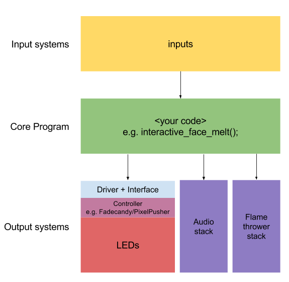
<p>If you are trying to win Burning Man, building an LED installation for a client to help fund a Burning Man project, or one of the more fringe reasons to embark on a large scale LED project, it’s probably more useful to think of your system like this:</p>

<p><a href="/assets/images/system-diagram-2.png"><img src="/generated/system-diagram-2-575-bf38712e3.jpg" alt="diagram" srcset="/generated/system-diagram-2-575-bf38712e3.jpg 575w" width="575" height="560"></a></p>

<p><em>Big installation conceptual view</em></p>

<p>Your unique core program captures the bulk of the complexity in your project. This could be taking a webcam feed, doing some real time video processing, based on sound input, and sending the output to an LED grid and sound system. Or it could be using motion sensing data to light up a stage and trigger flames when certain dance move combos are detected. Your core program will most likely be written in a high level language, such as Python or Processing. This program will likely access the hardware (including LEDs) through a more general interface.</p>

<p>For example, a microcontroller library such as FastLED includes a lot of framework code to make animation and colour related calculations easier. This make sense as your animation code would be running on the same processor as your LED library. However the flip side is that the library can only directly interact with C/C++ code that’s running on the same controller. To interact with another program, running on a different computer, you’d need to get radios, networks, and serial ports involved.</p>

<p>A more generalised LED output stack, as we outline later, will only allow most simple commands, such as specifying that LED 34 is set to the colour that corresponds to the RGB triplet (127, 0, 127). However, this interface can be access by almost any program, often across a network.</p>

<p>–Not sure how this read–</p>

<p>The interface between your program (referred to as “client”) and the LED subsystem (referred to as “server”) is usually the ability to set an LED (addressed by an integer) a certain colour (specified as a RGB triplet). It’s up to the server code to translate that down to well timed signals to the LEDs. The client is responsible for ensuring that the intention of the program is carried out. This means that, among other things, the client need to be aware of the physical geometry of individual LEDs, and their relation to each other.</p>

<p>For the purposes of this article, we’ll discuss three solutions:</p>

<h2 id="fadecandy">Fadecandy</h2>

<p><a href="http://www.misc.name/fadecandy/">Fadecandy</a> is the brainchild of Micah Elizabeth Scott. She developed the WS2812 only system while working on a Burning Man installation. The system comprise of:</p>

<ul>
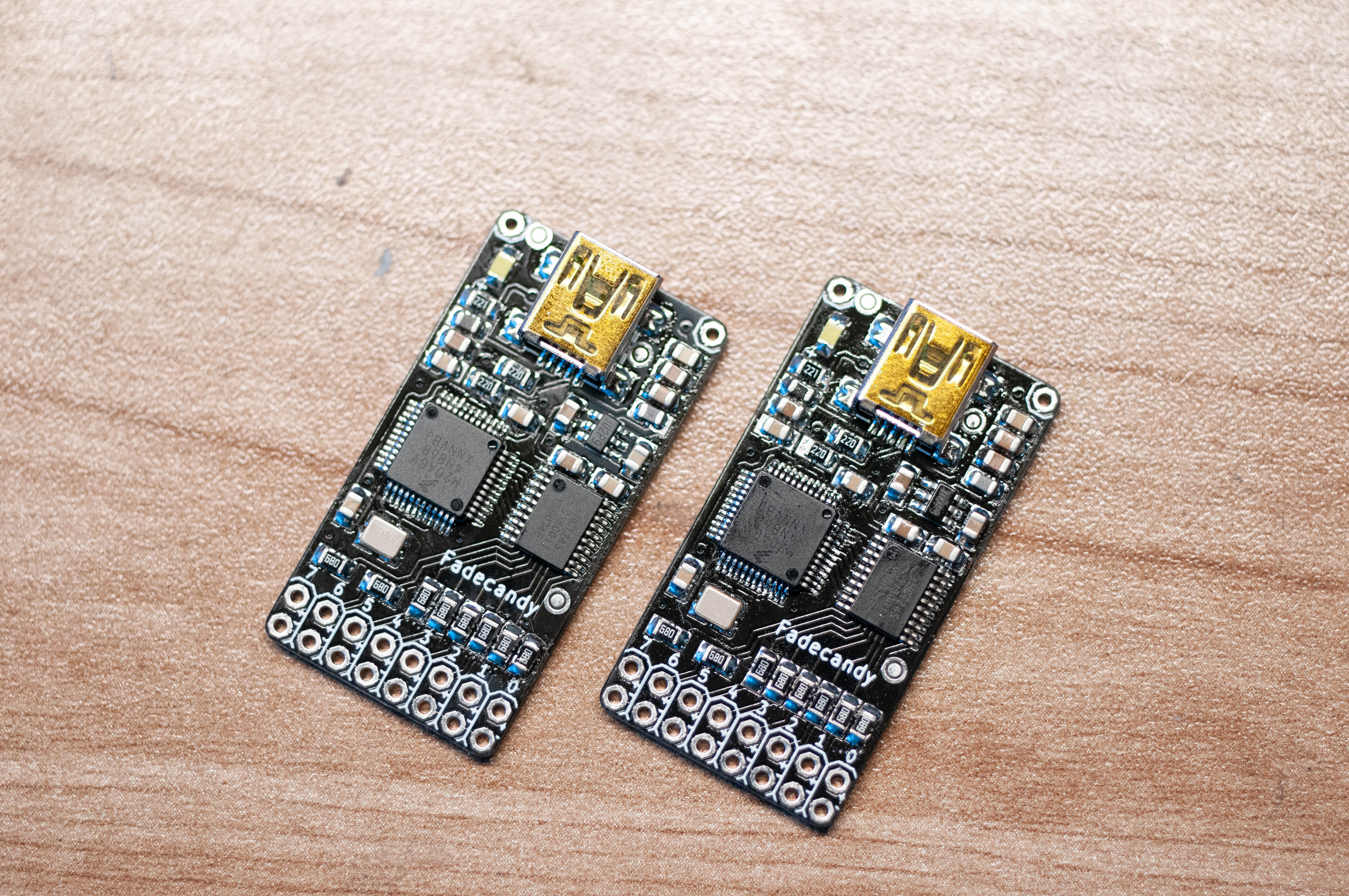
  <li>A custom designed board, based on a Teensy 3.0. It connects to a host system running Linux, OSX or Windows via USB. This is manufactured and sold by Adafruit. Each board can control up to 512 LEDs.</li>
  <li>Custom firmware on the board that improves the range of colours possible from WS2812s, and smoother animations.</li>
  <li>Server software that exposes the LEDs over Open Pixel Control protocol over the network.</li>
</ul>

<p>The client could run on practically any platform, and written in any language, as long as it can communicate via TCP sockets.</p>

<p>The system is very accessible: each Fadecandy board costs $25, and that gets you up and running. When installed, aRaspberry Pi could be used to the server, controlling upwards of 10 000 LEDs.</p>

<h2 id="ledscapergb-123-cape">LEDscape/RGB-123 Cape</h2>

<p>This system is used in many Burning Man installations, and is a combination of several projects. It comes together to expose 1000s of WS2812 LEDs through an Open Pixel Control server, using a BeagleBone Black (BBB) as both the LED controller and server. The components are:</p>

<ul>
  <li><a href="https://beagleboard.org/black">BeagleBone Black</a>, a computer by BeagleBoard that is similar to, and somewhat more powerful than a Raspberry Pi. Significantly, it contains two Programmable Realtime Units, or PRUs. These can run with enough timing precision to control WS2812b LEDs.</li>
  <li>Ryan O’Hara’s <a href="http://rgb-123.com/shop/">BBB output capes</a>, sold through his RGB-123 shop. These handle level shifting, comes in 24 or 48 strand configurations. Significantly, there is also a version that uses the RS-485 standard to extend the signal via Cat6 cables and RJ45 connectors.</li>
  <li><a href="https://github.com/Yona-Appletree/LEDscape">LEDscape</a> library, originally written by Tremmel Hudson, and forked by Yona Appletree. This contains all the softare, from PRU firmware up to an OPC implementation. This also includes some of the same firmware tweaks that Fadecandy has.</li>
</ul>

<p>As with the Fadecandy system, there is huge amount of flexibility in terms of what technology the client can use. In fact, LEDscape and Fadecandy could share client code without any modification.</p>

<p>This system has a slightly higher cost of entry, with output capes costing from $35 upwards, in addition to the cost of a BBB ($55). However, it’s becomes competitive with Fadecandy above a scale of approximately 1500 LEDs.</p>

<h2 id="on-a-tangent-open-pixel-control-and-processing">On a tangent: Open Pixel Control and Processing</h2>

<p>This pair of technology is widely used for LED control.</p>

<p>Many large LED projects are written in <a href="https://processing.org/">Processing</a>, a Java based language geared at creative coding. It provides easy access to graphics and input handling, but loses some of Java’s more robust testing/compiling tools.</p>

<p><a href="http://openpixelcontrol.org/">Open Pixel Control</a> (OPC) protocol is used by various projects as the interface between core program and the LED stack. It’s very easy to implement, and Micah Scott’s Processing client implementation, and her example projects are widely used.</p>

<h2 id="pixelpusher">PixelPusher</h2>

<p>This is the last of the trio of LED systems this article will discuss. Shockingly, it’s also developed for Burning Man projects, by <a href="http://ledlabs.squarespace.com/">Christopher Schardt</a>. It differs from LEDscape and Fadecandy by being both a bit more flexible, but also closed source and commercial.</p>

<ul>
  <li><a href="http://www.heroicrobotics.com/products/pixelpusher">PixelPusher</a> (v3) controller, is the hardware component. It’s a custom ARM board that can control most types of LEDs, including all four types covered in Part 1 of the article. Each unit can control 8 strands of LEDs, and connects to a network via a RJ45 socket.</li>
  <li>The PixelPusher protocol, which allows for easier configuration of multiple PixelPushers as part of the same installation. The vendor also provides tools to bridge control across to DMX, the dominant system for professional theater and stage lighting. The vendor provides a Processing library for client code.</li>
  <li>If you don’t want to write a client program, there is <a href="https://itunes.apple.com/us/app/l.e.d.-lab/id832042156?mt=8">L.E.D. Lab</a>, an iPad App that acts as a default client for the system. The app includes a selection of built-in effects.</li>
</ul>

<p>The cost of entry for the system is similar to that of LEDscape, with each PixelPusher unit costing $120. But, at 5000+ LEDs scale, LEDscape may be cheaper.</p>]]></content><author><name>Shen Tian</name></author><summary type="html"><![CDATA[Originally posted on Medium]]></summary></entry><entry><title type="html">Addressable LED tech atlas: Part 1</title><link href="https://shentian.me/2016/05/22/LED-tech-pt1.html" rel="alternate" type="text/html" title="Addressable LED tech atlas: Part 1" /><published>2016-05-22T00:00:00+00:00</published><updated>2016-05-22T00:00:00+00:00</updated><id>https://shentian.me/2016/05/22/LED-tech-pt1</id><content type="html" xml:base="https://shentian.me/2016/05/22/LED-tech-pt1.html"><![CDATA[<p><a href="/assets/images/led-reel.jpeg"><img src="/generated/led-reel-600-684f2699a.jpg" alt="header image of a reel of LEDs" srcset="/generated/led-reel-600-684f2699a.jpg 600w, /generated/led-reel-1200-684f2699a.jpg 1200w" width="1366" height="768"></a></p>

<p><em>Originally posted on <a href="https://medium.com/@shentian/addressable-led-tech-atlas-part-1-17729d66e04a">Medium</a></em></p>

<p>So, you want to play with addressable LEDs! Whether it’s for home decor, <a href="https://www.youtube.com/watch?v=B-mrleAj3Xs">wearables</a>, <a href="https://www.youtube.com/watch?v=wmBvObbwLmE">a hula hoop</a>, <a href="http://www.instructables.com/id/Make-an-interactive-iPad-controlled-LED-Wall/">making a video wall</a> or <a href="https://www.inverse.com/article/5814-the-10-best-burning-man-2015-projects-nd-how-they-work"><em>winning</em> Burning Man</a>, they are great fun. However, once you know what you want to do with them, you need to decide what hardware and software to do it with. As often is the case, there’s no right and wrong choices, but there are better and worse choices. This can be quite daunting, so when the loud man at your maker meetup insists that “You should totally use a PixelPusher to drive some 2801s, but roll your own app in Processing”, like they did for their project, is it right for you? What is a PixelPusher? Is it larger than a duck? Can you git clone it? Is the man actually an Oracle salesperson who arrived at the wrong venue, is trying to sell you an enterprise license to something?</p>

<p>With this guide, I aim to provide a survey of significant technology choices, and a view of why people would prefer one over the other for their application. It assumes that you’ve gotten some LEDs to light up with an Arduino, or read through a guide for a project that you like. However, you’d like some help in joining the dots, and helping you decide on what hardware and software to bring together for your next LED project. It aims to provide breadth in the form of comparisons of techs, rather than depth of actual how-tos: those are already done much better than I can hope to achieve elsewhere. Furthermore, I’ll aim to cover the more popular options, because I believe that they are often better by the virtue of having more community discussion and support. If what you need is more niche, I hope this guide will help you answering the question of “Why won’t X work for you?”, which should help you find your right specialised solution.</p>

<p>I would suggest that you use this article as follows:</p>

<ol>
  <li>Find a project guide on what you’d like to do. As with many things maker, Adafruit does an excellent job of producing and curating a <a href="https://learn.adafruit.com/category/leds">wide selection</a>. <a href="http://www.instructables.com/id/LEDs/">Instructables</a> has an even wider range of projects to look at.</li>
  <li>If the guide helps you to achieve what you want, great! This article will be simply too much information.</li>
  <li>If what you’d like to achieve is different from the guides you are using as references, or you want to figure out if there are simpler, better, or just different ways to do that, use this article to understand why the authors might have chosen what they did, what else they could have chosen, how their requirement may differ from yours, and therefore, what might be some good avenues of exploration for you.</li>
</ol>

<p>The article is compromised of two parts. The first (this part) covers most small/medium sized projects you’d want to undertake. This will cover the different types of LEDs, the electronics you’ll need to control them, libraries to help you program them, and a bit on how to power them.</p>

<p>The second will cover the extra technology pieces involved in more complex, less commonly seen projects, that require extra layers of abstraction (see: <em>winning Burning Man</em>). This would include dedicated hardware, network protocols and libraries for wider range of languages.</p>

<h2 id="the-leds">The LEDs</h2>

<p>There are many types of addressable LEDs out there, but I’ll focus on four:</p>

<ul>
  <li>WS2812: mostly seen in its WS2812b form, but also marketed as NeoPixels by Adafruit. These have become the de-facto standard for addressable RGB LEDs, used from wearables all the way up to giant installations. They are cheap, bright, compact and only require three wires. These factors have combined to make them wildly popular. The WS2812 contains a chip called WS2811, so you can see these used somewhat interchangeably.</li>
  <li>APA102: mostly seen in its APA102c form, marketed as DotStars by Adafruit. These are the new kid on the block. They are as compact as WS2812s, will have less flicker, works with Pis directly. However, they are more expensive and require four wires.</li>
  <li>WS2801 and LPD8806: think of these are precursors to the APA102s: four wires, relatively easy to control, but because the chips are separate from the LEDs, they are more bulky.</li>
</ul>

<p><em>Which one?</em> The default option is the WS2812s, if only because they are so widely available, cheap, and require 25% less soldering. If you have to mounting on them on something that moves fast and generate light trails (<a href="https://www.youtube.com/watch?v=BaJwohtZMtA">OMG LED Hula Hoops</a>), have a look at the APA102s. The APA102s are also good if you need to control them directly into a Raspberry Pi. Use the older WS2801s or LPD8806s only if they are cheaper, more available, or come in a specific packaging you need.</p>

<p>On three v.s. four wires: the WS2812’s most distinct feature is that it requires only three wires. This means less cabling, less soldering and smaller connectors. As a consequence of this design choice, though, it need to be controlled by a very precisely timed signal, otherwise it will glitch/flicker more, or just not work outright. Something like a Raspberry Pi will be too busy running Linux (or similar) to be able to guarantee the precision required. Typically, we’ll use an Arduino-like board to do the job.</p>

<h2 id="microcontroller-and-libraries">Microcontroller and Libraries</h2>

<p>For most applications, you will want to control the LEDs using just your microcontroller of choice. This could be an <a href="https://www.arduino.cc/en/main/arduinoBoardUno">Arduino</a> (or equivalent), <a href="https://www.pjrc.com/teensy/">Teensy</a> or even an <a href="https://en.wikipedia.org/wiki/ESP8266">ESP8266</a>. There just a few things to note:</p>

<ul>
  <li>It often takes more memory/faster processor to control more LEDs. However, you are unlikely to hit any limit until you have 500+ LEDs. The exception is the smallest boards, such as the <a href="https://www.arduino.cc/en/Guide/ArduinoGemma">Arduino Gemma</a>, which only has 512 bytes of RAM, in comparison to 2kb in an Arduino Uno, or 64kb in a Teensy 3.2. These boards can only handle around 100 LEDs.</li>
  <li>Different boards send signals out at various voltages, whereas almost all LEDs are designed to receive signal at 5V. Therefore, something called a level shifter might be required for 3.3V (or lower) boards.</li>
</ul>

<p>The task of converting the C code you write to actual signals sent to the LEDs along IO pins is typically done by a library. Unless you have a very good reason to, don’t try to do this yourself — this is a very general, but also solved, problem. You should probably be using one of these:</p>

<ul>
  <li>Adafruit’s libraries: Adafruit provides libraries for <a href="https://learn.adafruit.com/adafruit-neopixel-uberguide/arduino-library-installation">NeoPixels</a> (WS2812), <a href="https://learn.adafruit.com/adafruit-dotstar-leds/overview#libraries-and-example-code">DotStar</a> (APA102), <a href="https://learn.adafruit.com/digital-led-strip/code">LDP8806</a> and <a href="https://learn.adafruit.com/12mm-led-pixels/code">WS2801</a>. They are used extensively in most of Adafruit’s excellent LED project tutorials, including the extensive <a href="https://learn.adafruit.com/adafruit-neopixel-uberguide/overview">NeoPixel Uberguide</a>.</li>
  <li><a href="http://fastled.io/">FastLED</a>: this is a more sophisticated library. It supports most LEDs and boards you can think of, and is maintained and supported by its own strong community.</li>
</ul>

<p><em>Which one?</em> Adafruit’s library is relatively basic, allowing you to specify colours via RGB values. It’s an excellent entry point, especially if you are following Adafruit’s tutorials. It also glues into their <a href="https://learn.adafruit.com/adafruit-neopixel-uberguide/neomatrix-library">Matrix</a> and <a href="https://learn.adafruit.com/adafruit-gfx-graphics-library/overview">Graphics</a> libraries, for basic animation work. However, if you find yourself writing or using a lot of framework code (e.g. animation, different ways to specify colour) to layer over the library, then it’s probably worth pausing and looking at what FastLED has to offer. This library has a slightly steeper learning curve, but provides a lot more built in functions, including HSV/RGB colour management, animation timing, and Perlin noise.</p>

<p>There are other libraries, such as <a href="https://www.pjrc.com/teensy/td_libs_OctoWS2811.html">OctoWS2811</a> and <a href="https://github.com/cpldcpu/light_ws2812">light_ws2811</a>. However, they target more fringe use cases. I’d suggest that you explore them only once you’ve ran into a limitation of the more popular libraries.</p>

<h2 id="raspberry-pi">Raspberry Pi</h2>
<p>When controlling the four-wire LEDs from a Raspberry Pi directly, there is still some work involved in turning higher level code to control signals. Some libraries that do this for the APA102 include:</p>

<ul>
  <li>Adafruit’s <a href="https://github.com/adafruit/Adafruit_DotStar_Pi">DotStar Pi</a>: a Python module</li>
  <li><a href="https://github.com/tinue/APA102_Pi">APA102_Pi</a>: another Python(3) module</li>
</ul>

<p>There are others libraries, of course, including ones for older LEDs. But as we are typically working with higher level languages on a Pi, with it’s megabytes of RAM, one would look at more general libraries for colour/graphic capabilities. The LED controller library has a smaller role to play.</p>

<h2 id="powering-leds">Powering LEDs</h2>

<p>The power requirement of having many LEDs add up very quickly. 10 WS2812s can draw up to 600mA, and a 5m strip of 60/m LEDs can draw up to 18A. Calculating your power requirement, and meeting that is a broader, electrical topic that goes beyond the scope of this article. However, a few popular approaches include:</p>

<ul>
  <li>
    <p>Most microcontroller boards will have a 5V or 3.3V pin that can supply at least 500mA. using this pin will typically provide the neatest solution in terms of wiring. If you limit LED brightness, this solution can carry you surprisingly far, but do the maths.</p>
  </li>
  <li>Direct battery power: a single cell Li-ion cell supplies between 3.3–4.2V, depending on chemistry and state of charge. This is often used for compact, wearable projects. Alternatively, AA or AAA batteries are also used. 3 Alkaline (non-rechargeable) or 4 lower voltage NiMH cells provide suitable voltage.</li>
  <li>Conveniently, USB is designed around 5V, and many solutions make use of that. A USB powerbank will often supply 1–2A at 5V, with the added benefit of safety cutoffs. Most cellphone chargers can also be used to supply 1–2A at 5V.
Larger projects will use AC/DC adapters to supply power from mains at 5V, or buck converters to provide 5V from a large (typically higher voltage) batteries.</li>
</ul>

<p>Next: Part 2 will cover more complex projects. These are typically bigger, both physically and in terms of number of LEDs. They also tend to have more complex control mechanisms, typically spanning a computer network.</p>]]></content><author><name>Shen Tian</name></author><summary type="html"><![CDATA[]]></summary></entry></feed>