Building a Fadecandy in 2023: Part 1
I’m doing some maintenance/planning for an existing project that makes use of over a dozen Fadecandy LED controllers. Given these have been out of production for a few years, why not take advantage of the fact that it’s open source, and make some myself?
The creator of Fadecandy, Micah Elizabeth Scott, aka scanlime, seems to have stepped away from the project. She has deleted much of the official content, including the github repo. As it happens, I’ve already started a lot of the planning work for these DIY Fadecandies, before the github repo was deleted. I debated a bit on whether it’s appropriate to do this write up, given that the project creator would rather not see it continue. In the end, I believe an aspect of open source is to decouple the creation from the creator. With that in mind, consider this a tribute to the project.
Objective
- Document what it takes to build a Fadecandy board in 2023
- Provide information that might be useful for people maintaining existing projects: updated instructions on
- How to build and flash the firmware
- How to build/run the host side software
- Show the project some appreciation
- Learn a few things for myself, and hopefully help one or two other people learn a few things.
Non-goals
- Any continuation/expansion/evolution of the project
- Producing more than a handful of new boards. Certainly nothing commercial
- Commitment to keeping any of the documentation up to date
Bill of Materials
The goal is a reasonably close reproduction of an Adafruit revision B board. The Eagle files were in the repo, and I believe this makes up for the vast majority of Fadecandies made.
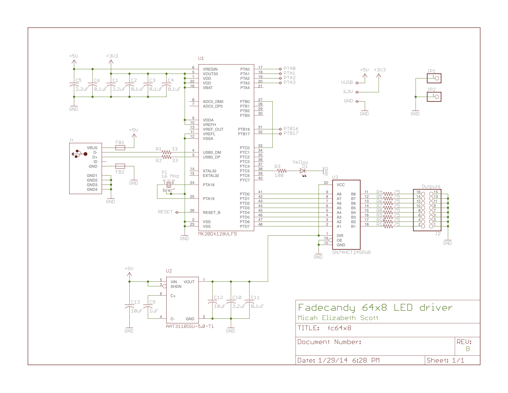
It’s worth noting that a Fadecandy, electrically, is based on a Teensy 3.0 + OctoWS2811 adapter, less Teensy’s two-chip bootloader setup, plus a 5V power supply. This will be useful in most component selection questions. I made good use of this forum thread.
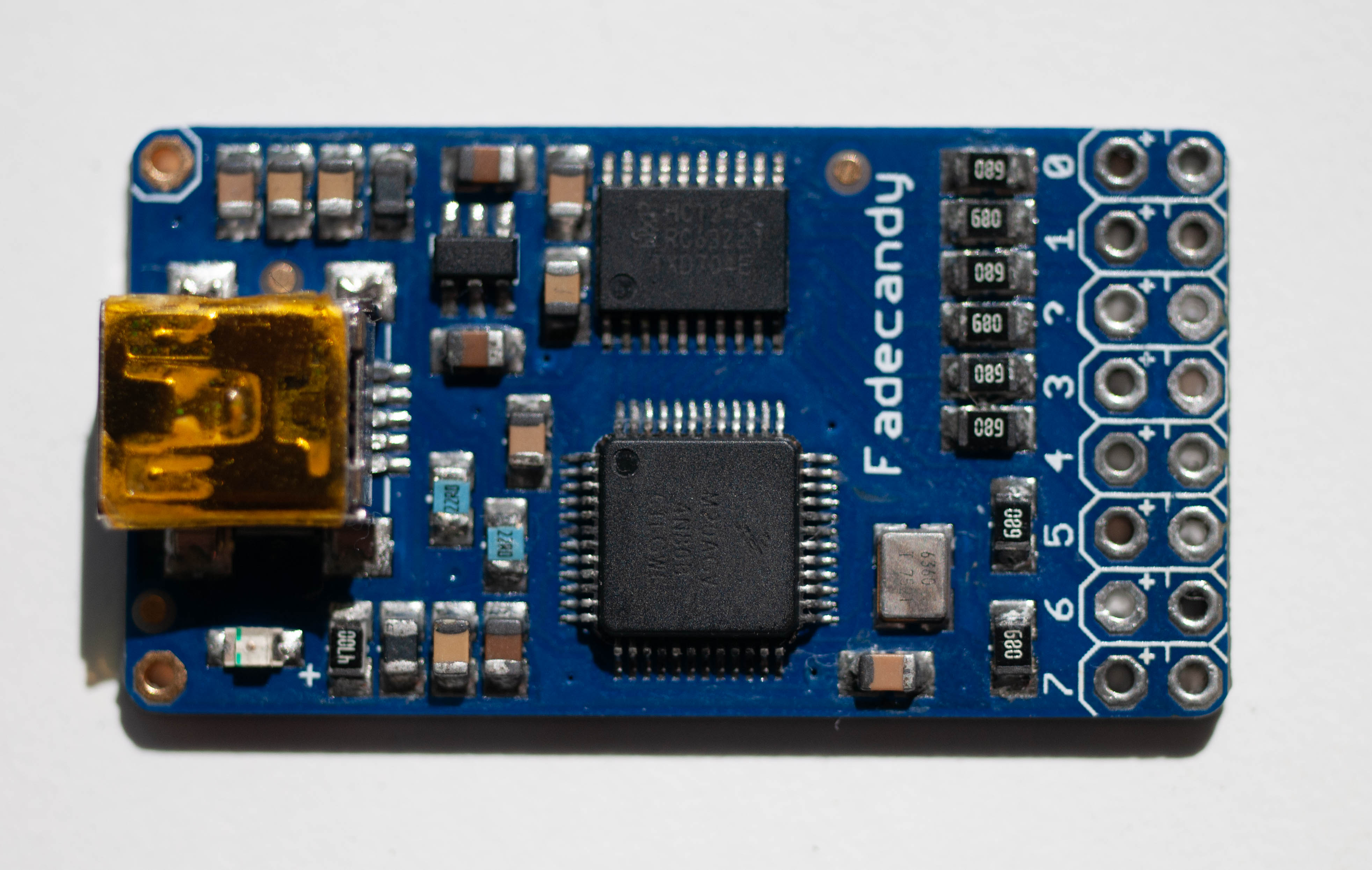
A example of a (water damaged and dead) Fadecandy rev b board
Working through the schematic…
Microprocessor and its crystal
The core of the board is a NXP MK20DX128VLF5 - this microprocessor was originally released by Freescale in the early 2010s. It’s part of the Kinetis K20 family. It consists of a 50Mhz Cortex M4 core, 128KB of flash, and comes in a 48 pin LQFN package. As of late 2023, it’s still listed as “Active” by NXP. Stock availability is a bit patchy. I manage to buy a handful after looking across a few shops via Octopart. I expect this will go obsolete at some stage, and it will become impossible to produce firmware compatible boards.
It uses a handful of MLCC capacitors for decoupling. I’m going with some X5R or X7R 0805 parts, rated at 16V or higher.
Selecting the crystal takes a little bit more research. It’s a 4-pin 3.2x2.5mm SMD part. The schematics label it at 16Mhz. We need to determine its accuracy, load capacitance, and ESR. Digging this and this forum threads, we arrive at 10ppm or less stability, a bit less than 10pF or load capacitance. Looking at parts on Digikey that fits this description, we are looking at probably at least 50Ohm ESR.
I learnt about matching load capacitors to crystals in the RP2040 Hardware design guide, so I was a bit surprised to see that that the schematic didn’t include any load capacitors. the second thread linked to above yielded the information that the K20 MCU has software configurable internal load capacitors. To find out what the Fadecandy uses, I searched the relevant register names in the repo, and found these lines in the bootloader code.
    // enable capacitors for crystal
    OSC0_CR = OSC_SC8P | OSC_SC2P;
i.e. 10pF load capacitor configured. If we assume 3pF for trace capacitance… that gives around 8pF for the crystal. This checks out with the “a bit less than 10pF” from above! (The RP2040 Hardware design guide has a good section on this calculation in page 9.)
With all the above information, I went with an Epson part rated at 9pF, 10ppm stability and 60Ohms ESR. As it happens, the RGB-123 PCB design files included a BOM, which specified a very similar part (slightly lower stability/tolerance).
Charge pump
The design takes account of the fact that VBUS is nominally 5V for USB, it could be a lot lower in practice, especially when long cables and self powered hubs are used.
It includes a Skyworks AAT3110IGU-5.0-T1 charge pump, 100mA @ 5V output. This is discontinued and unavailable as of 2023. However, this is a jellybean part, and there are plenty of alternatives, though this might require different complementary passives.
I’ve replaced this with a MPS MP9361, 110mA @ 5V pump. This operates at 1.35Mhz, v.s. 750Khz of the Skyworks part. The only thing this will need to drive is the level shifter, which has a max supply draw in the region of 70mA (though I suspect it’s a lot lower in practice).
The reference design in the datasheet specifies a 0.47uF capacitor for flying cap (C9 in the schematic). The equation for flying capacitor values does suggest that capacitance being inversely proportional to frequency, so this makes sense. The datasheet also had different values for input/output caps, but those don’t have to be as exact, so I’ll leave them as they are.
The fact that this IC comes in a T(hin)SOT-23-6 package, whereas the original is a regular (thick?) SOT-23 doesn’t matter, as it’s purely a height issue.
Level shifter
This is responsible for shifting the 3.3V logic from the MCU up to 5V expected by WS2811 controllers. The schematic specifies a Texas Instruments SN74HCT245PWR Octo bus transceiver. This is available in large numbers as of 2023. As a member of the 7400 family, it’s likely to be made for the foreseeable future. In fact, the boards made by Adafruit used Nexperia 74HCT245PW versions. I used that version, as I had those on hand.
USB connector
The board uses a mini-B USB connector. It’s a common SMD footprint. I used a EDAC part that matched the Adafruit boards.
The connector has Ferrite Beads on the VBUS and GND lines. Going through forums, Paul suggested 600Ohm @ 100Mhz parts.
Hacker port
Lastly, the bottom of the board has a programming/debug header, in the form of 10 square test pads in a 2x6 2.54mm pitch array. One could easily solder onto these… but I ordered a spring loaded connector that I’ll build into a jig.
Resistor changes
A visual inspection of the Adafruit boards I have show 22Ohm resistors for R1 and R2 (USB D+/D-) instead of the 33Ohm components in the schematic. I have no idea why, and chances are, it’s not crucial. I’m going to err on what went onto the manufactured boards.
The current limiting resistor for the indicator LED is 470Ohm instead of 180Ohm. This might be related to the schematic specifying a yellow LED, whereas the boards are populated with a green one… though those two colours tend to have similar forward voltages (~2.1V), so it might just be there to make it a bit less bright. This is also unlikely to be critical. I ended up swapping the LED to a white one, and used a 220Ohm resistor.
Lastly, the Eagle files specified 68Ohm for R4-R11. This matches the boards I have. However, the PDF schematic used 75Ohm. I’ve gone with 68Ohms. These resistors are there to reduce ringing, as discussed here. There is no right value, as it depends on what you are going to wire the board up to.
(Modified) Bill Of Materials
This decisions described above. For the capacitors and resistors, I included a Digikey part number as an illustration of a suitable part, but anything in spec would have worked (probably).
| Ref | Description | Manufacturer | Part number | Digikey |
|---|---|---|---|---|
| C1, C5, C12, C13 | Cap Cer 10uF 16V X5R 0805 | 1276-1096-1-ND | ||
| C2-C4, C6, C11 | Cap Cer 0.1uF 50V X7R 0805 | 1276-1003-1-ND | ||
| C9 | Cap Cer 0.47uF 16V X7R 0805 | 1276-6483-1-ND | ||
| C10 | Cap Cer 2.2uF 16V X7R 0805 | 1276-1162-1-ND | ||
| D1 | White 0805 | 3147-B1701TW–20P000314U1930CT-ND | ||
| FB1, FB2 | 600 Ohms @ 100 MHz, Signal Line Ferrite Bead 0805 | Bourns | MH2029-601Y | MH2029-601YCT-ND |
| J1 | USB - mini B USB 2.0 Receptacle Connector 5 Position Surface Mount, Right Angle | EDAC | 690-005-299-043 | 151-1206-1-ND |
| R1, R2 | Res SMD 22Ohm 5% 1/8W 0805 | 311-22ARCT-ND | ||
| R3 | Res SMD 220Ohm 5% 1/8W 0805 | 13-RC0805JR-13220RLCT-ND | ||
| R4-R11 | Res SMD 68Ohm 5% 1/8W 0805 | 311-68ARCT-ND | ||
| U1 | ARM® Cortex®-M4 Kinetis K20 Microcontroller IC 32-Bit Single-Core 50MHz 128KB (128K x 8) FLASH 48-LQFP (7x7) | NXP | MK20DX128VLF5 | MK20DX128VLF50-ND |
| U2 | Charge Pump Switching Regulator IC Positive Fixed 5V 1 Output 110mA SOT-23-6 Thin, TSOT-23-6 | MPS | MP9361DJ-LF-Z | 1589-1744-1-ND |
| U3 | Transceiver, Non-Inverting 1 Element 8 Bit per Element 3-State Output 20-TSSOP | Nexperia | 74HCT245PW,118 | 1727-6353-1-ND |
| X1 | 16 MHz ±10ppm Crystal 9pF 60 Ohms 4-SMD, No Lead | Epson | TSX-3225 16.0000MF09Z-AC0 | SER4069CT-ND |
My impression of the design
- It uses a Mini USB type B plug, though by 2013, Micro USB was already dominant (USB type C was only 2 years away!). I believe this is done for mechanical robustness.
- 0805 components: these are huge! Not sure why this was chosen, as Adafruit’s SMD lines could certainly have handled small components.
- The 68 Ohm resistors didn’t use a resistor array component.
Manufacturing
(I’ve also converted the Eagle files to KiCad. The process was somewhat manual, but nothing especially interesting.)
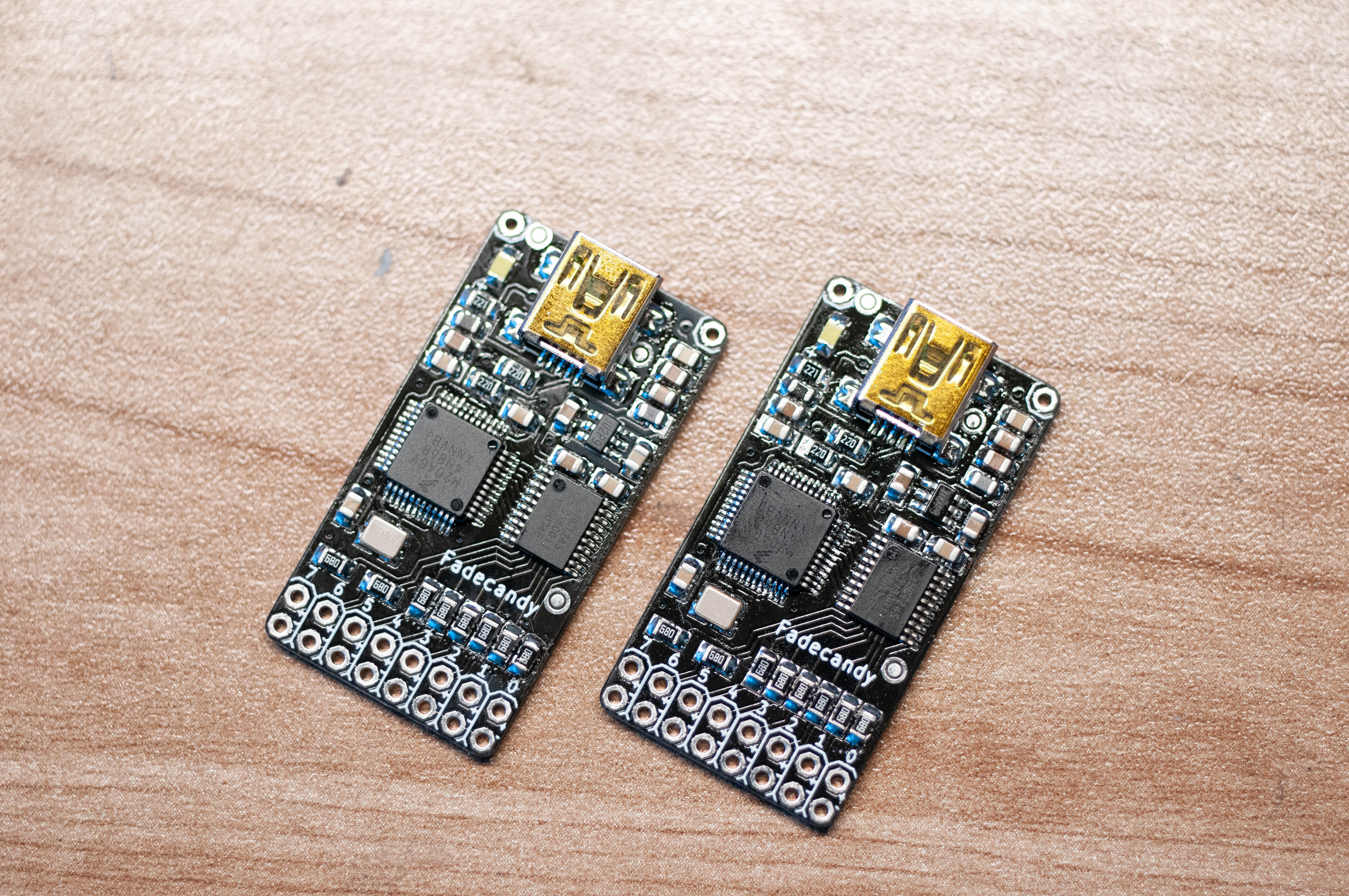
I ordered the boards and a stencil from JLCPCB. It looks like hand soldering the board should be possible, but I didn’t try.
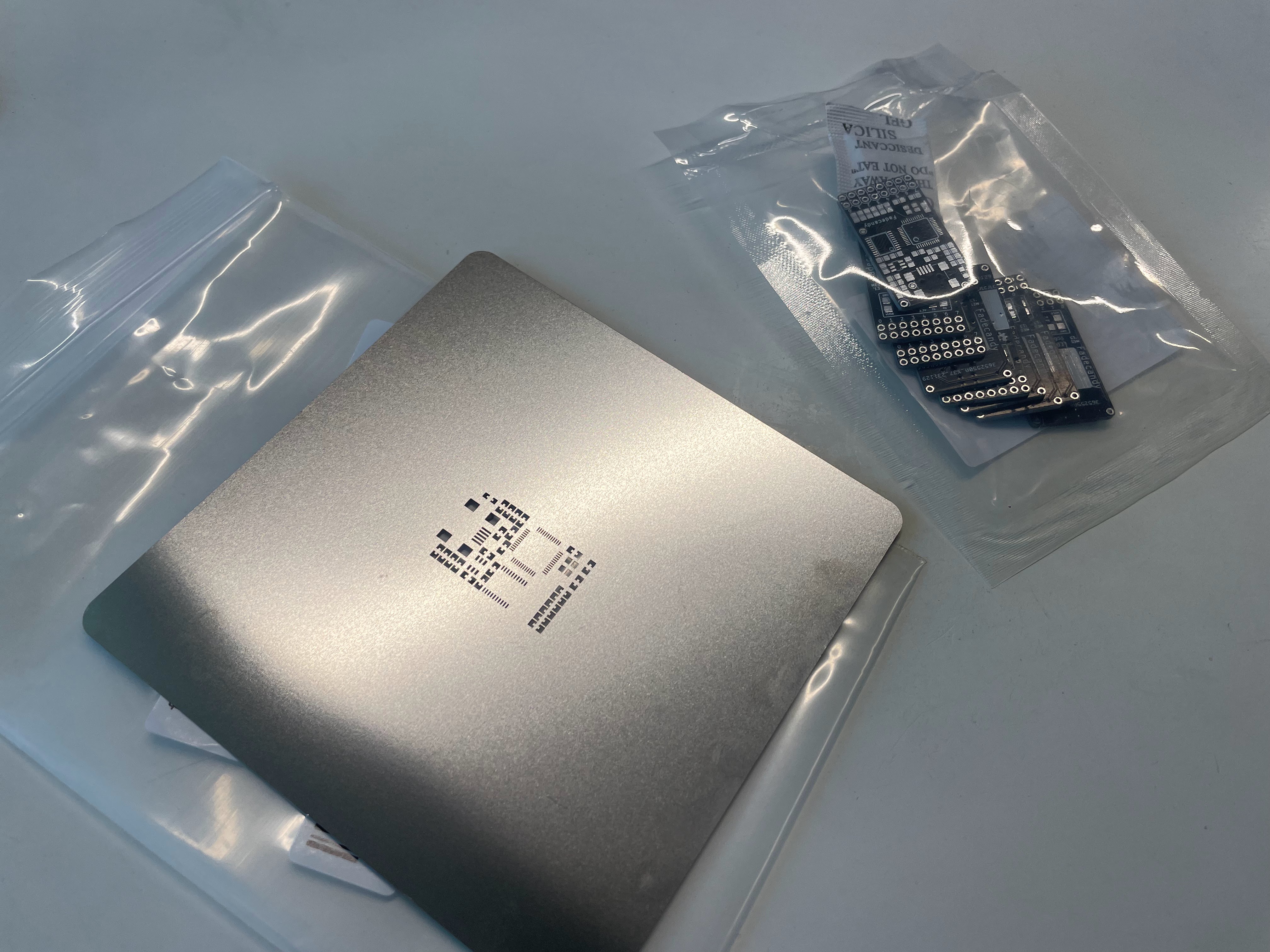
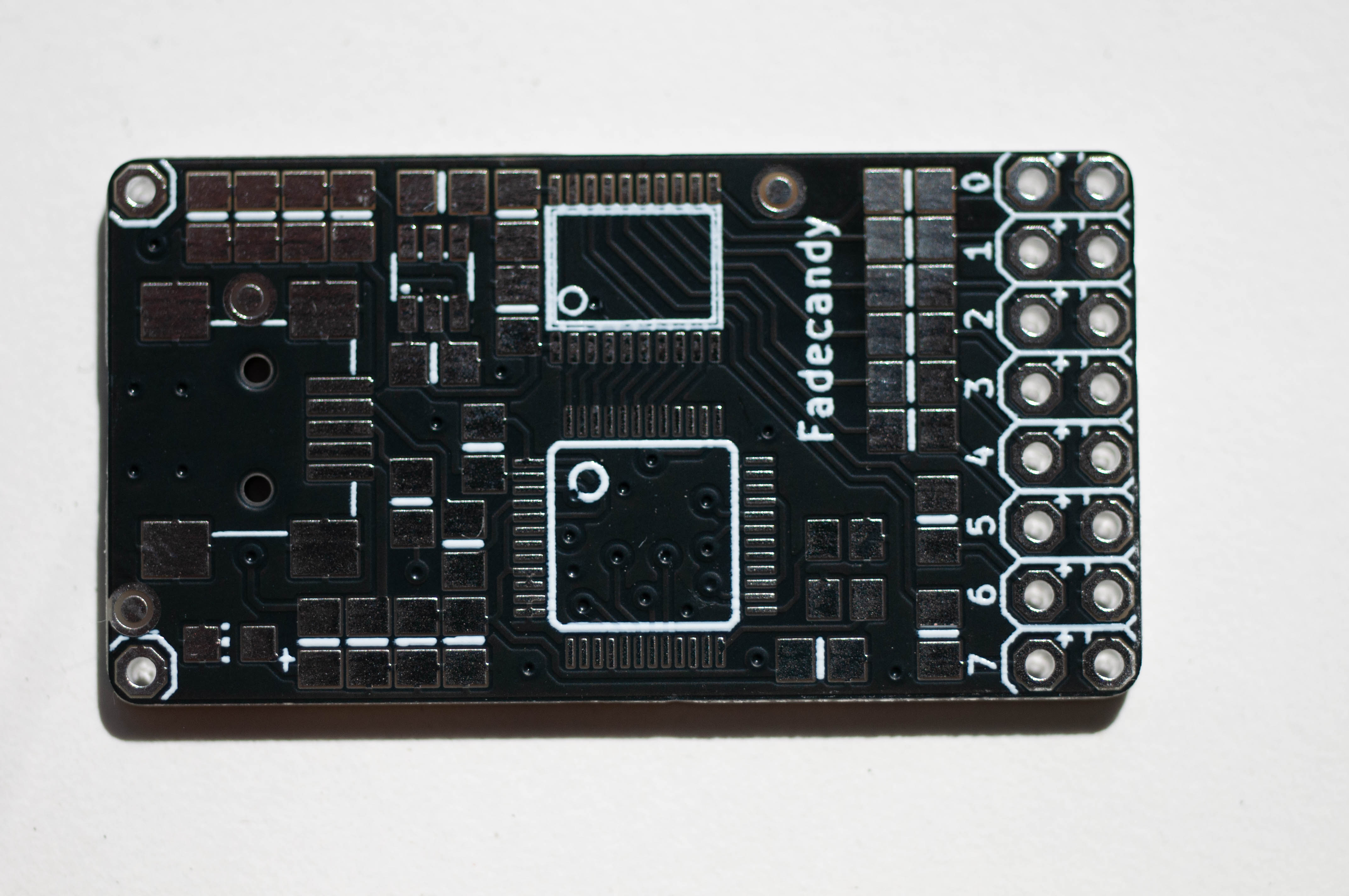
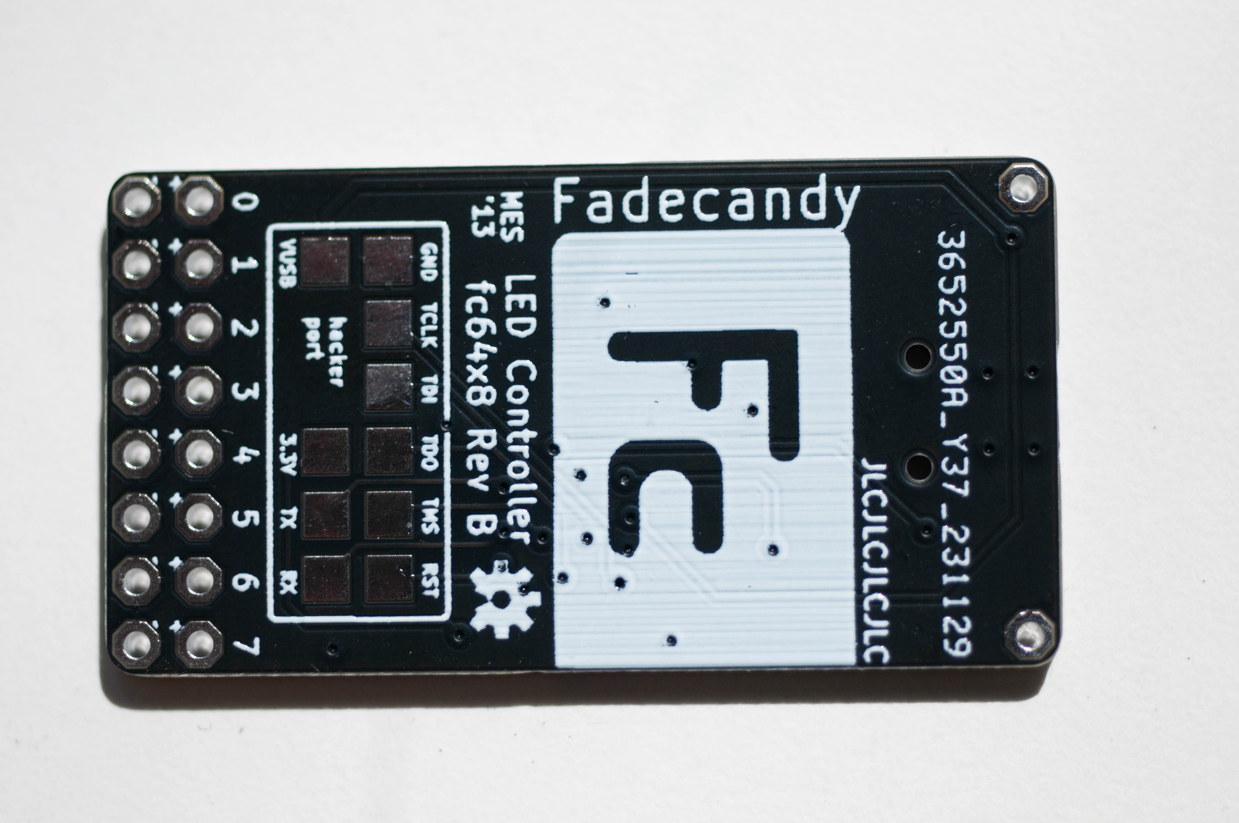
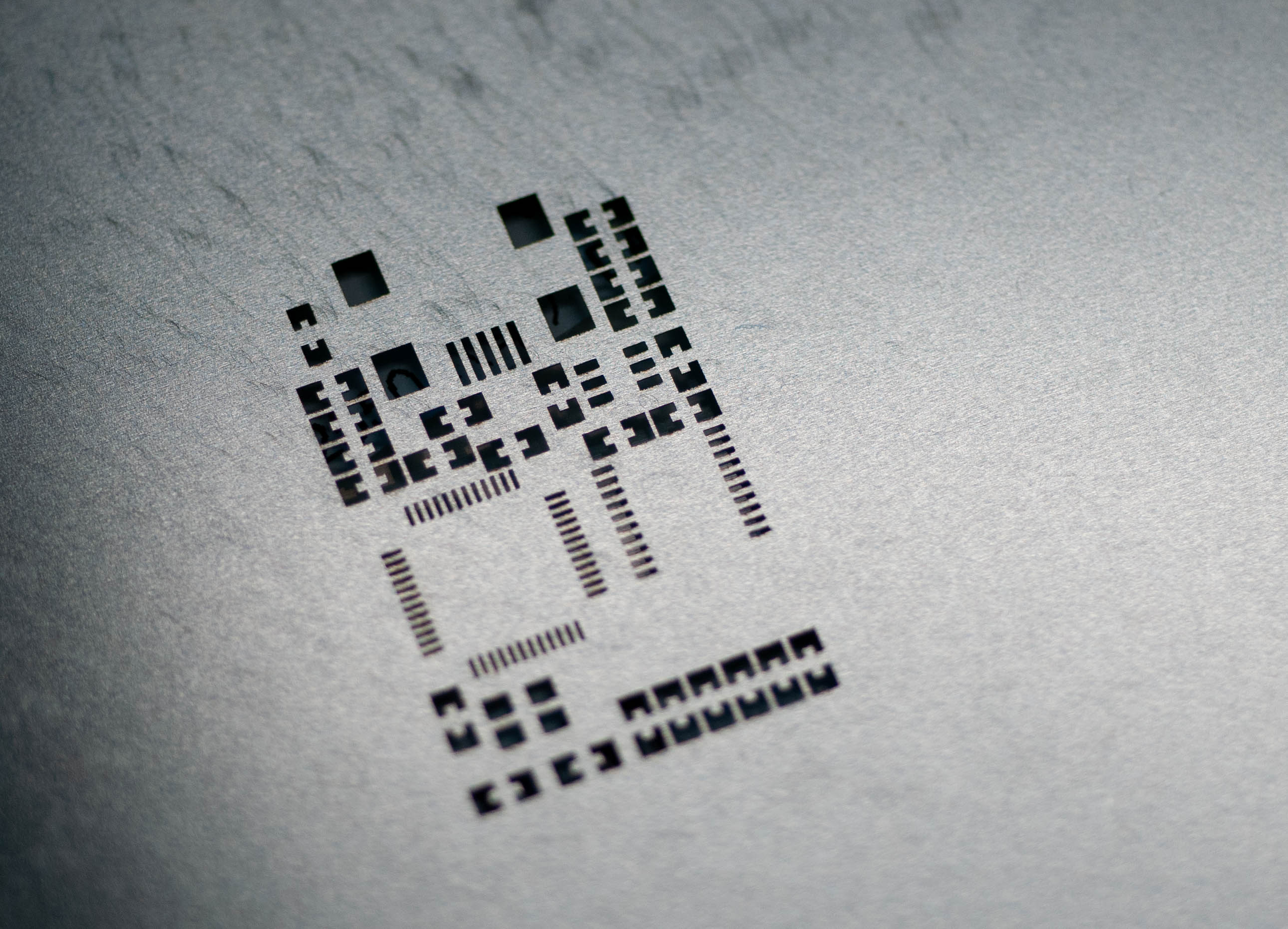
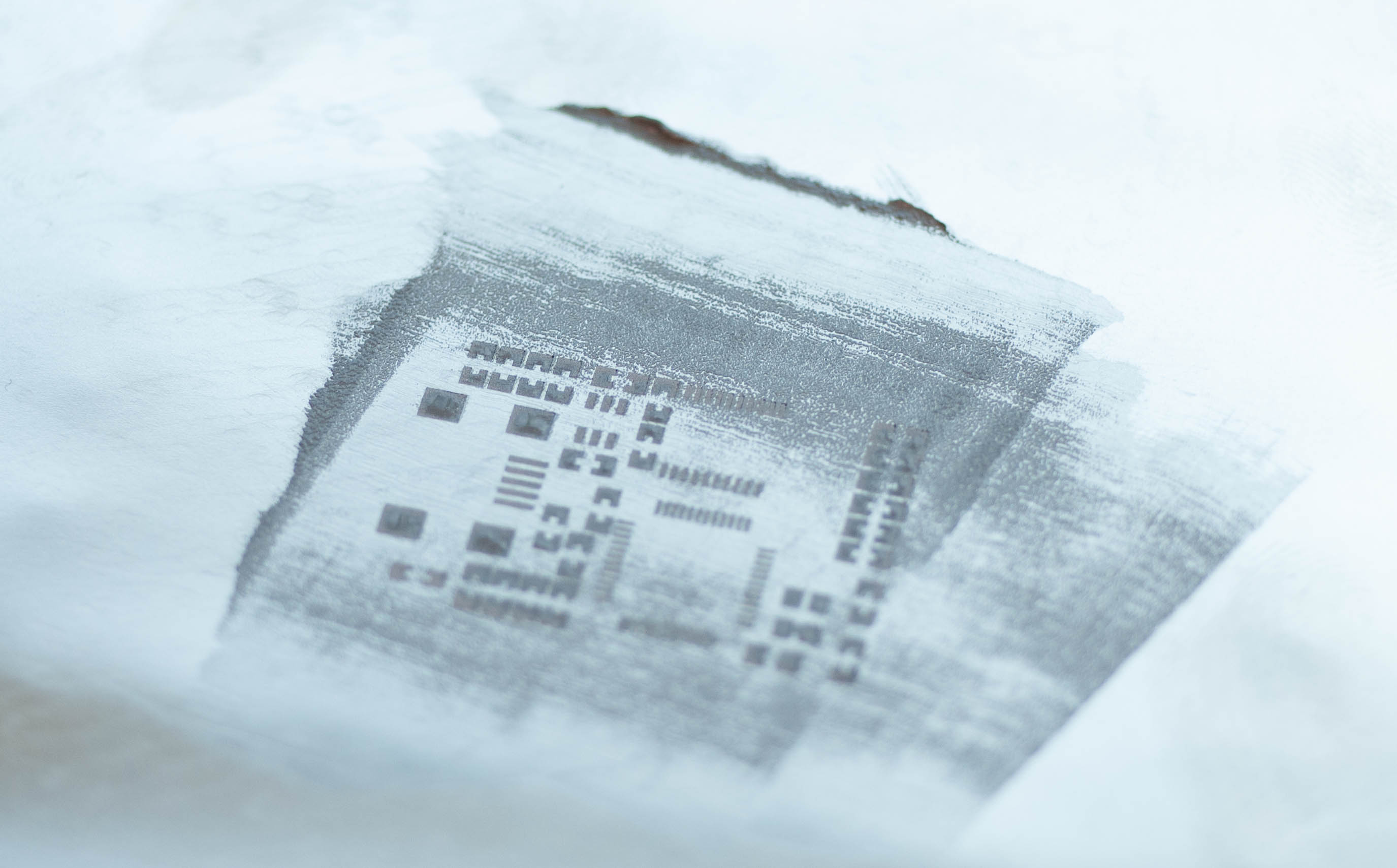
I applied the paste using a vacuum rig to hold the stencil flat. It wasn’t as neat as it should have been. I’m still figuring out the vacuum method.
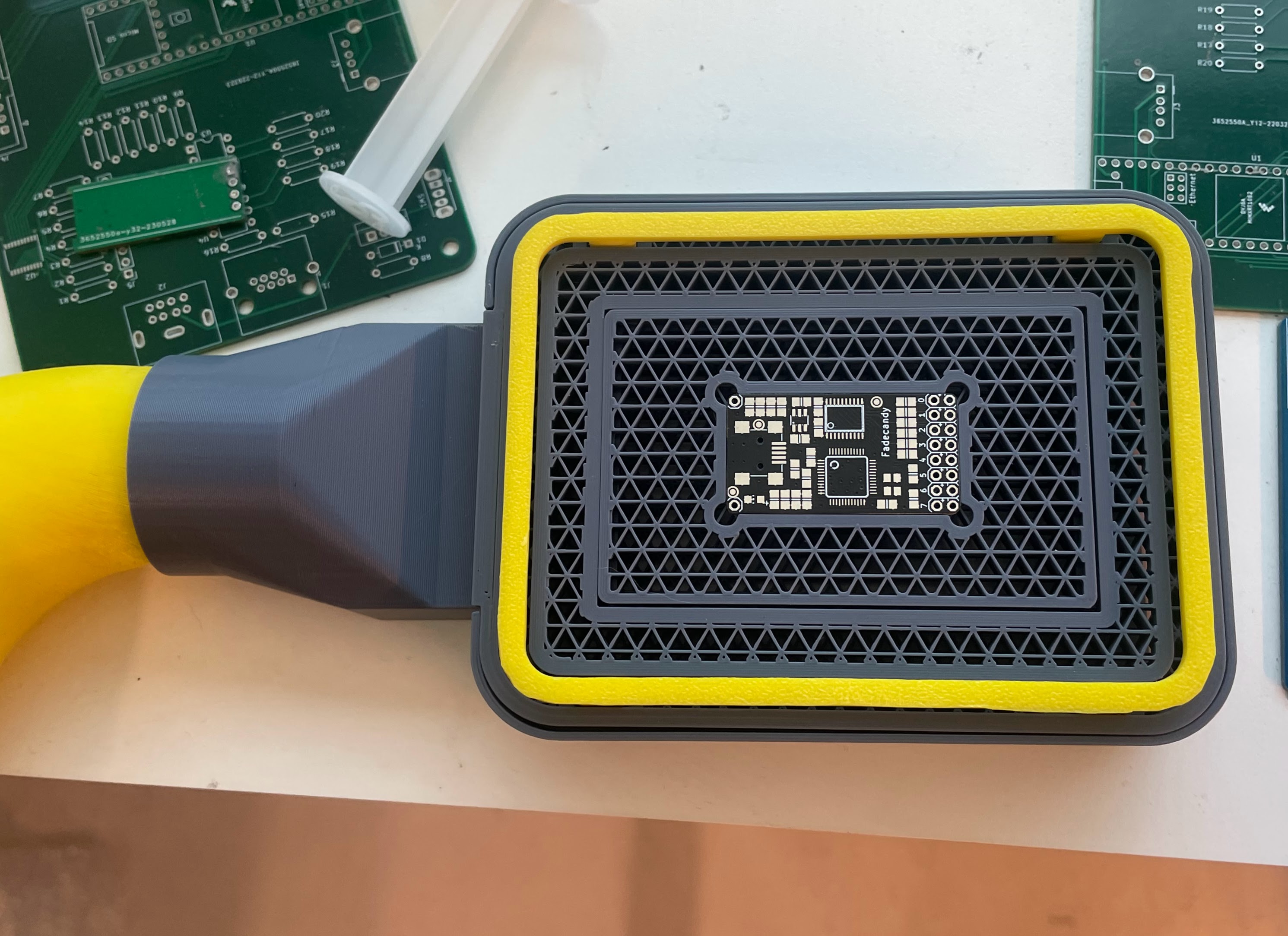
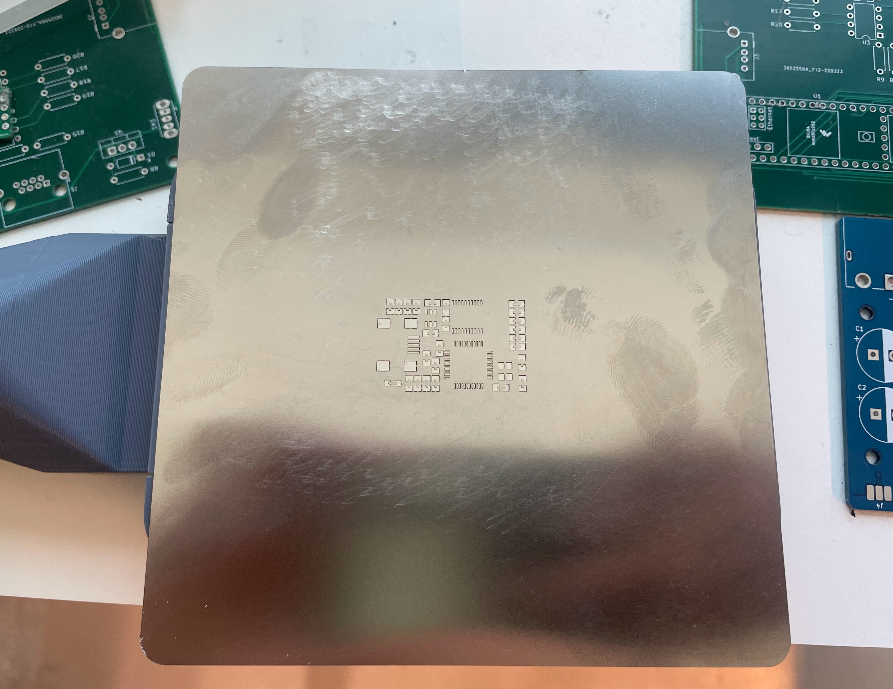
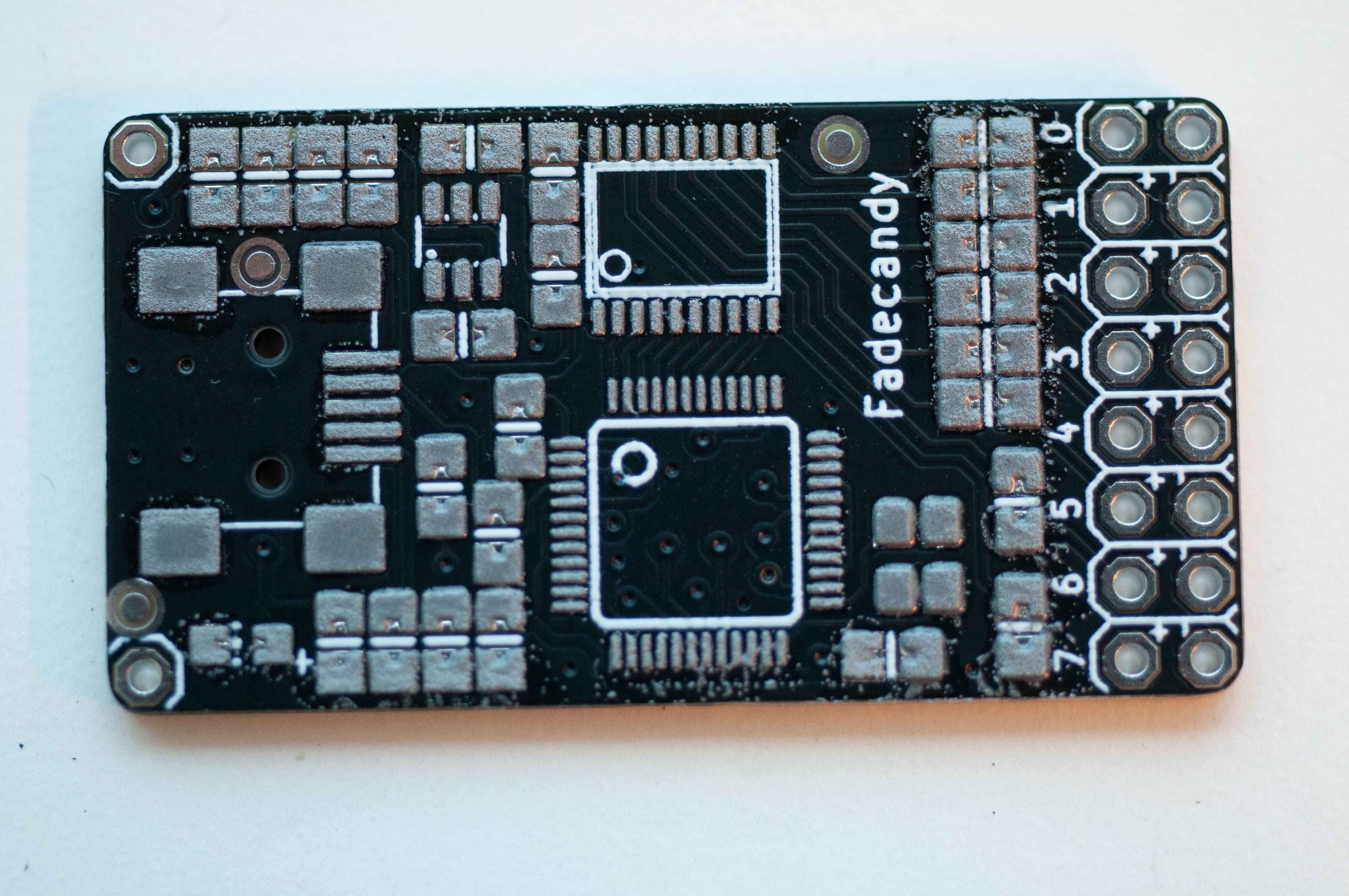
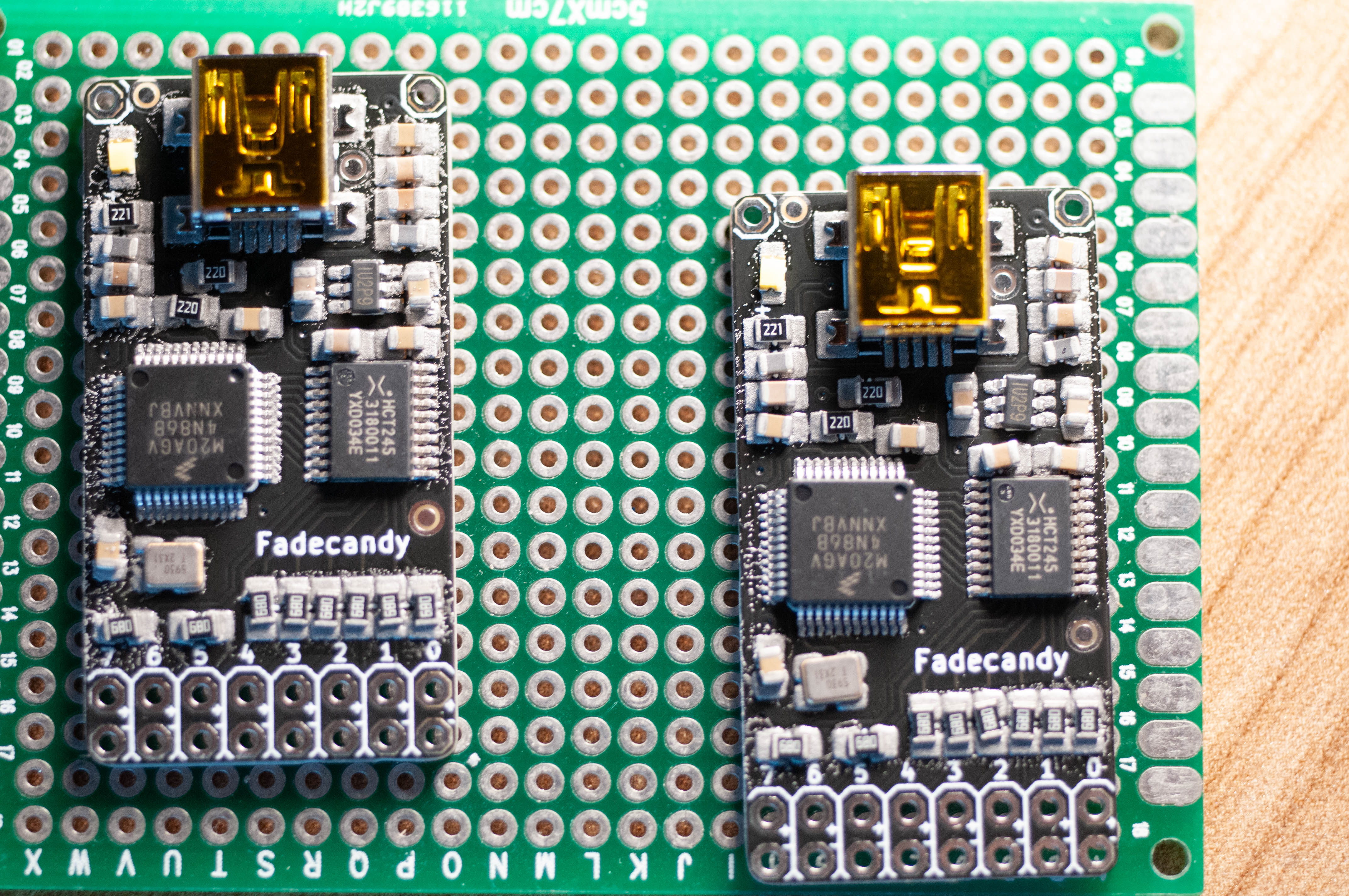
This was all reflowed on an Aliexpress 100x100mm hot plate.
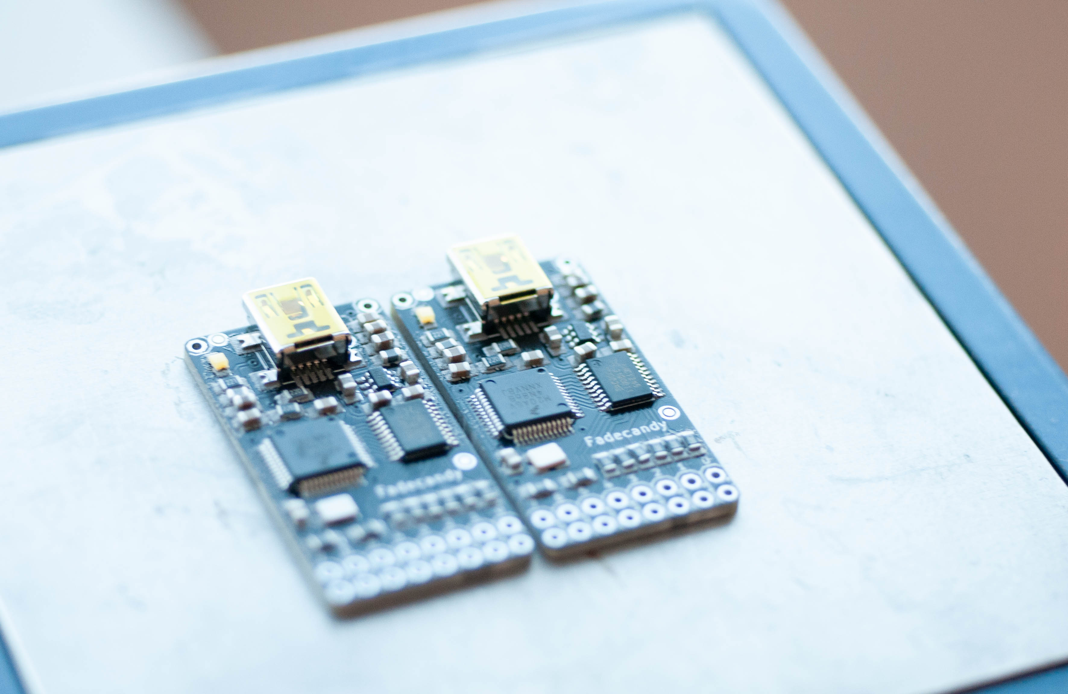
There was some reworking needed to remove a few bridges around the LQFP package.
Next part: programming!