Building a Fadecandy in 2025: Part 2
Well it’s been a while… let me say I got distracted from this project for a while. In the 18 months since Part 1, AI has made the job a lot easier than it would have been otherwise, but all commands were human verified – or at least, it worked on at least one two of my computers.
In Part 1, I documented the process of manufacturing my own Fadecandy boards, including converting design files from Eagle to KiCad, creating a BOM (filling in some missing details), and building a few boards.
Overview
In this part, I’ll flash the Fadecandy firmware onto the new boards we made in Part 1, using a SWD programmer and a custom jig. This will be followed by how to building the host software (fcserver), and how to build the firmware from source, and flashing it via USB.
Everything was tested on both Intel (macOS 11) and Apple-Silicone Mac (macOS 15). My fork of the fadecandy repo is here.
Writing to a blank board
The ability to flash firmware via USB is a standard part of the Arduino developer experience. For this to work, a small program called a bootloader need to be present on the MCU. This is either flashed at the factory, or built in at a silicon level (e.g. RP2040). The MK20DX128, fresh from the factory has neither, so we’ll need to go a different route - JTAG/SWD, a low level protocol that allows direct write to MCU flash.
We need some extra hardware to do this. I’m going to use a Segger J-Link EDU Mini programmer. There are several versions of this - though I believe the main difference is the type of USB connector. This has a standard ARM 10-pin JTAG connector. I’ve used an adapter to break it out to 0.1” pins, to facilitate connecting it to the Fadecandy’s programming ports (a.k.a. its hacker port)
The Teensy 3, on which the device is based on uses a second, auxiliary MCU to handle the USB programming. This second MCU, with it’s proprietary firmware, is the magic sauce that makes a board a Teensy.
hacker port
The hacker port is a set of pads on the back side of the board. I’ve used a 0.1” pitch 2x6 pin pogo connector to make contact. The pins are unnumbered. Each contact is defined as its own test point in the PCB design file. For the sake of this post, I’ve numbered them as follows:
Here’s a pinout
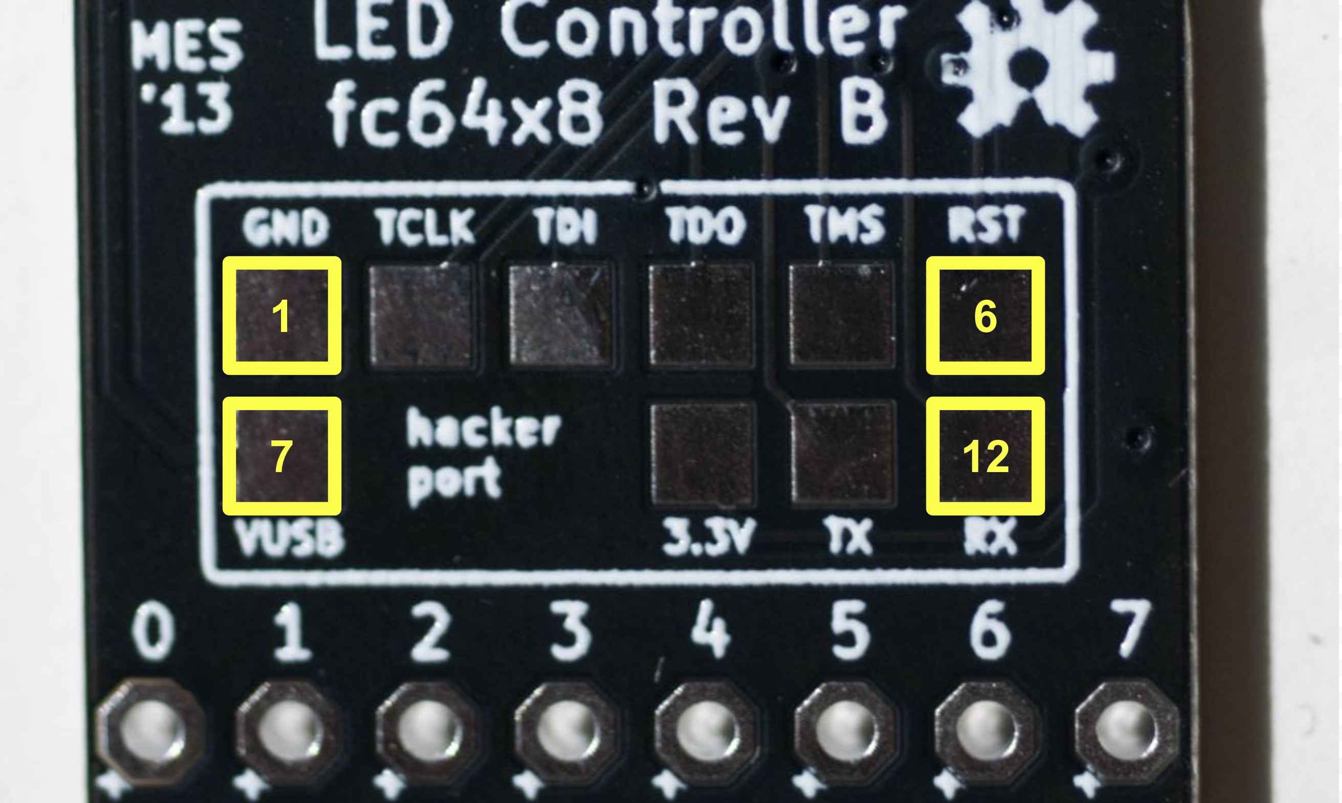
| # | Label | Purpose |
|---|---|---|
| 1 | GND | Ground reference |
| 2 | TCLK | JTAG clock/SWD CLK |
| 3 | TDI | JTAG data-in (not used by SWD) |
| 4 | TDO | JTAG data-out/SWD trace |
| 5 | TMS | JTAG mode/SWD data |
| 6 | RST | Active-low MCU reset |
| 7 | VUSB | 5V from USB jack |
| 8 | No connection | |
| 9 | No connection | |
| 10 | 3.3V | Regulated 3.3V |
| 11 | TX | UART0 TX |
| 12 | RX | UART0 RX |
Only five of these pins need to be connected to the JTAG connector for SWD
| J-Link 9-pin | Fadecandy pad | Comment |
|---|---|---|
| 1 Vref | 3.3V | Don’t feed power here – board must already be USB-powered |
| 2 SW(D)IO | TMS | |
| 4 CLK | TCLK | |
| 10 !RST | RST | |
| 3/5/9 GND | GND | at least one solid ground |
I built the following jig
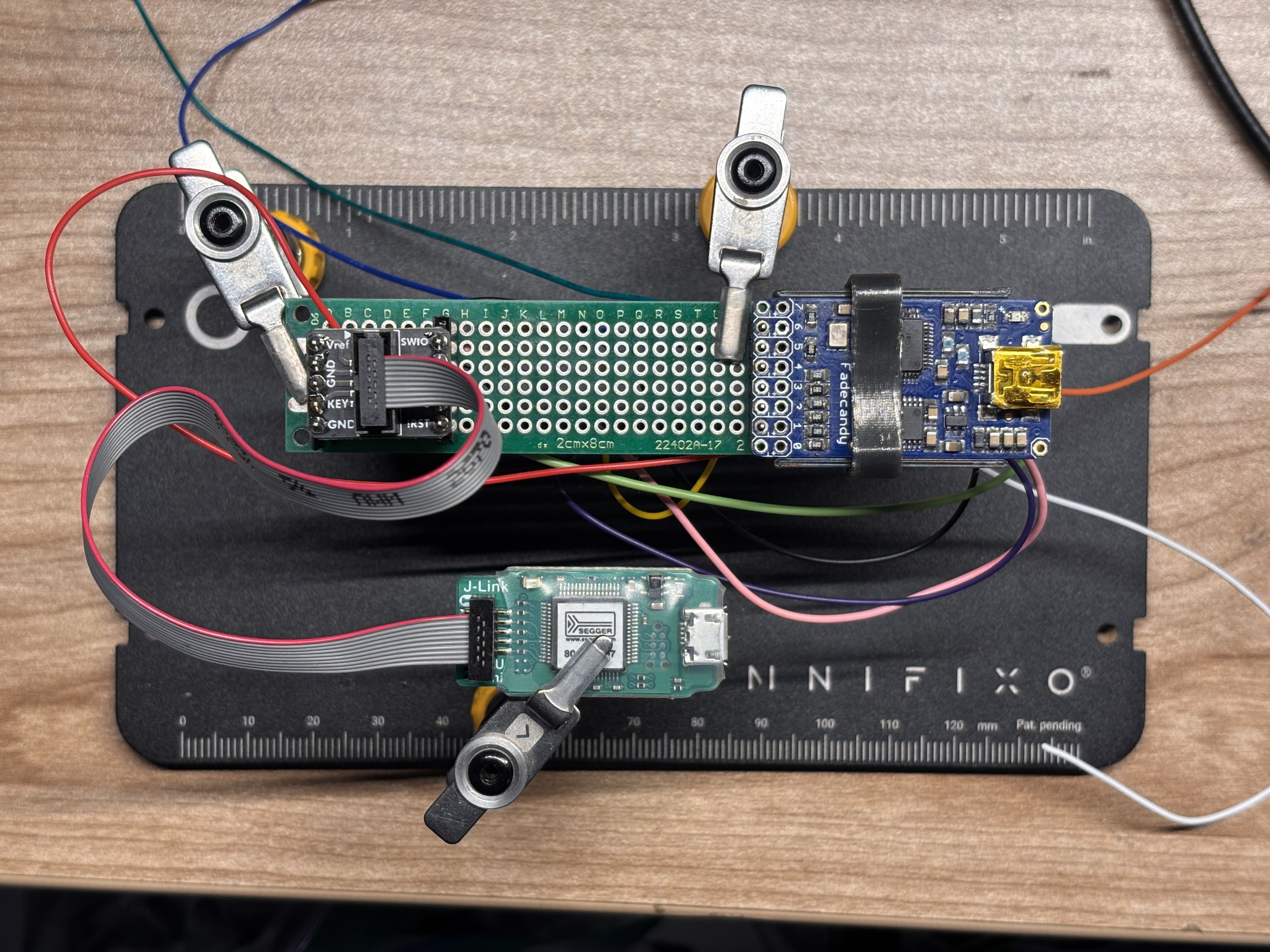
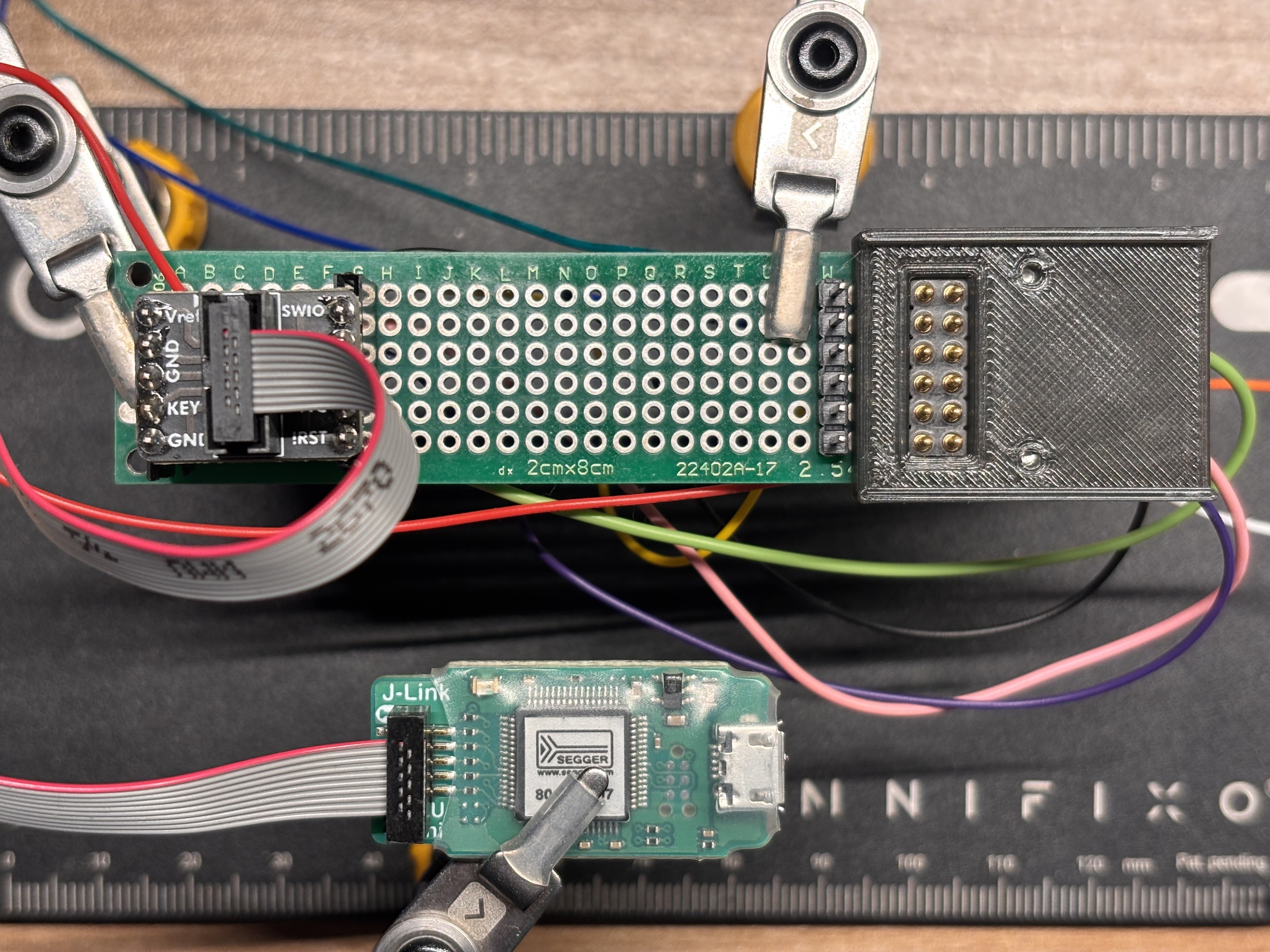
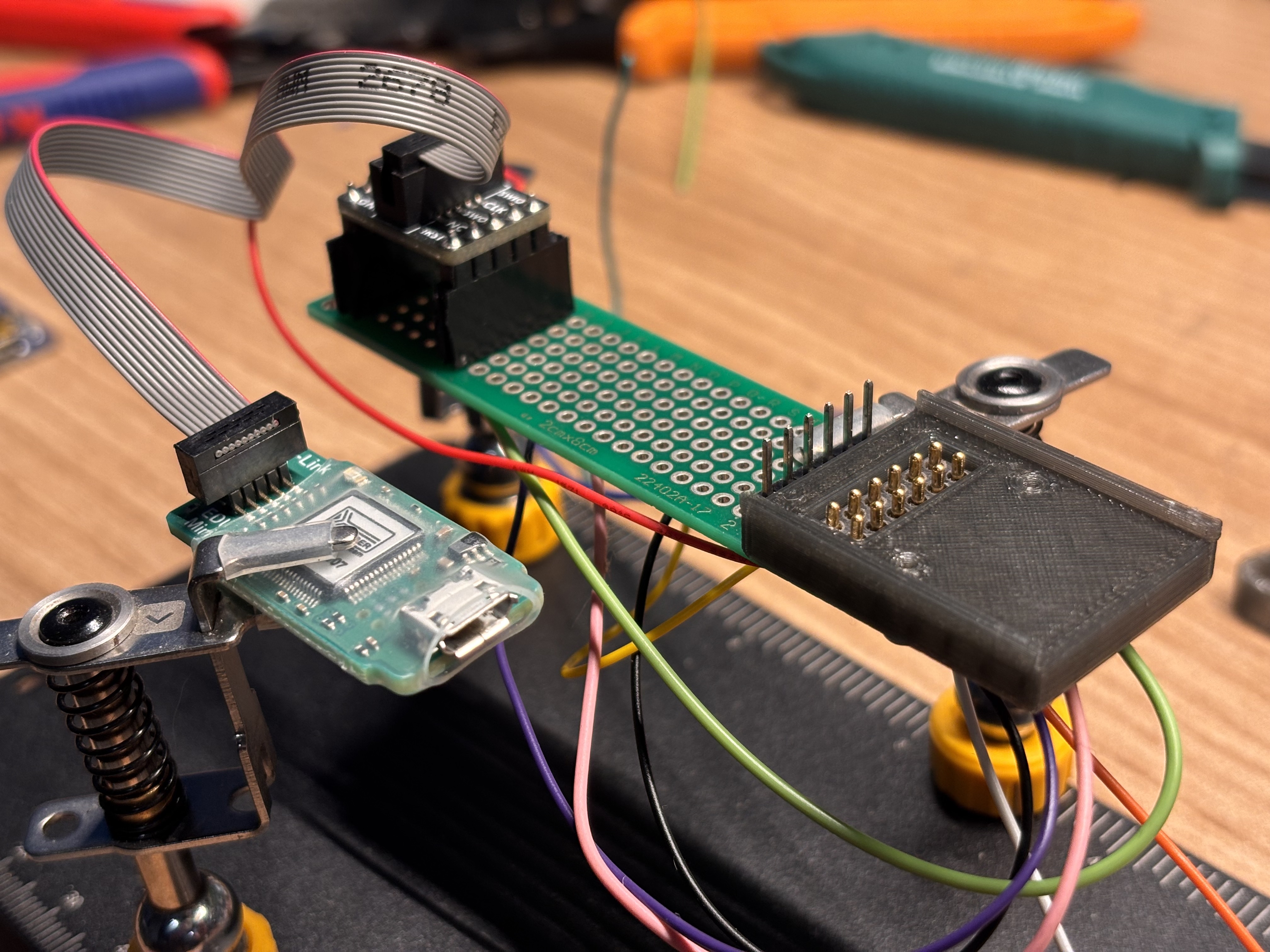
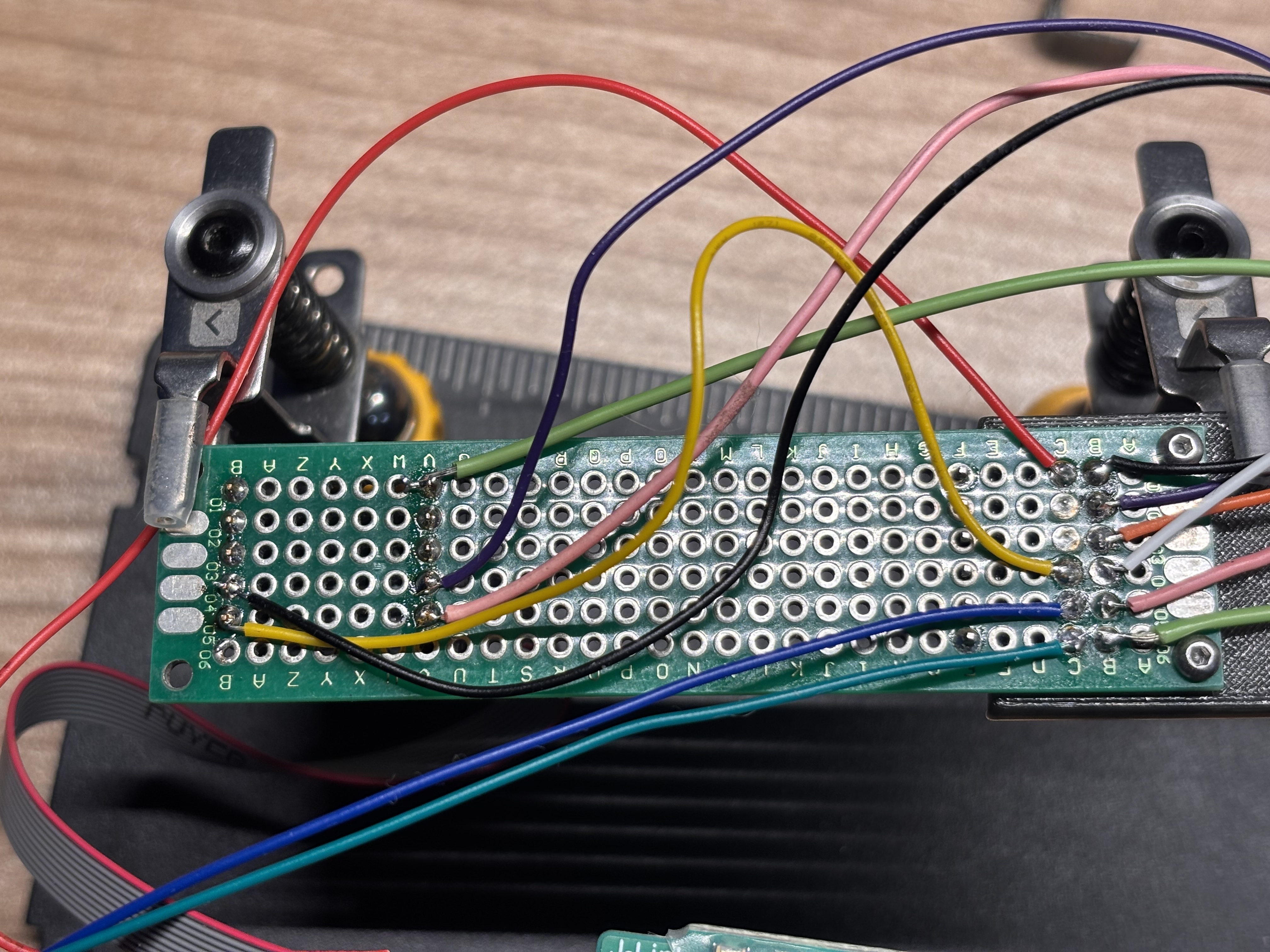
It’s an Omnifixo in case you are were wondering.
Before flashing the bootloader, both the J-Link and Fadecandy need to be plugged into USB - the later just for power.
We’ll use OpenOCD to do the flashing. On macOS, run brew install openocd to install. We’ll want a config file to make this easier. Using bootloader/openocd.cfg as a starting point, we create the following config file:
content of openocd_jlink.cfg
# openocd_jlink.cfg  –  use with:  openocd -f openocd_jlink.cfg -c "program PATH_TO_HEX verify reset exit"

# 1. Interface: use SEGGER J-Link rather than the Olimex FTDI probe
source [find interface/jlink.cfg]

# 2. Tell the J-Link we’re speaking SWD, not JTAG
transport select swd

# 3. Keep the target definition (k40.cfg handles all K20/K40 variants)
set CHIPNAME mk20dx128        ;# or just 'k40' – pick one name
source [find target/k40.cfg]

# 4. SWD clock. 1 MHz is safe on a breadboard; faster once wiring is short
adapter speed 1000

# 5. Mass-erase & program in one go
init; kinetis mdm halt; kinetis mdm mass_erase
A few things to note:
- Lots of link rot in the original file! Thankfully, they all seem to refer to patches to OpenOCD to make it work with the chip. 12 years down the line, mainline OpenOCD seems to work fine. Thank you open source contributors!
- A few commands have changed - better defaults? support of the
kinetis mdmcommands?
to flash it, run
openocd -f openocd_jlink.cfg -c "program ../bin/fc-firmware-v107.hex verify reset exit"
from the bootloader folder. This flashes the final factory firmware that Adafruit shipped (1.07).
You should see something like this:
Open On-Chip Debugger 0.12.0
Licensed under GNU GPL v2
For bug reports, read
	http://openocd.org/doc/doxygen/bugs.html
Info : add flash_bank kinetis k40.pflash
Info : J-Link EDU Mini V1 compiled Jun  6 2023 10:50:57
Info : Hardware version: 1.00
Info : VTarget = 3.277 V
Info : clock speed 1000 kHz
Info : SWD DPIDR 0x2ba01477
Info : [k40.cpu] Cortex-M4 r0p1 processor detected
Info : [k40.cpu] target has 6 breakpoints, 4 watchpoints
Info : MDM: Chip is unsecured. Continuing.
Info : starting gdb server for k40.cpu on 3333
Info : Listening on port 3333 for gdb connections
[k40.cpu] halted due to debug-request, current mode: Thread
xPSR: 0x01000000 pc: 0xfffffffe msp: 0xfffffffc
Info : MDM: Chip is unsecured. Continuing.
[k40.cpu] halted due to debug-request, current mode: Thread
xPSR: 0x01000000 pc: 0xfffffffe msp: 0xfffffffc
Info : Kinetis MK20DX128xxx5 detected: 2 flash blocks
Info : 1 PFlash banks: 128 KiB total
Info : 1 FlexNVM banks: 32 KiB total, 32 KiB available as data flash, 2048 bytes FlexRAM
Info : Disabling Kinetis watchdog (initial WDOG_STCTRLH = 0x01d3)
Info : WDOG_STCTRLH = 0x01d2
** Programming Started **
Info : Padding image section 0 at 0x00000ee4 with 284 bytes
Info : Flash protection requested in the programmed file differs from current setting.
Info : Data flash protection requested in the programmed file differs from current setting.
Info : Trying to re-program FCF.
** Programming Finished **
** Verify Started **
** Verified OK **
** Resetting Target **
Info : MDM: Chip is unsecured. Continuing.
shutdown command invoked
This should allow the board to enumerate on USB. To verify, run
system_profiler SPUSBDataType | grep -i -A3 -B3 "fadecandy"
we see
      Host Controller Driver: AppleT8132USBXHCI

        Fadecandy:

          Product ID: 0x607a
          Vendor ID: 0x1d50
That’s it! This should work like a Fadecandy from the shops! The binary included the custom (and DFU compatible) bootloader, so subsquent firmware updates can be via USB.
Host software
For a Fadecandy to work, we also need host software to connect to it over USB. fcserver is the provided and most commonly used one, as documented in the Adafruit guide. The guide is very loud and clear that the code no longer works on 64 bit systems. A trivial change fixes this.
Of more significance, the soure made use of some git submodules which are no longer at their original location on github. I’ve included them in my fork.
A simple make should build fcserver now.
Open Lighting Architecture (OLA) is actively maintained, and have built in Fadecandy support. I have not tested this.
Building and flashing the firmware
We can disconnect the J-Link and remove the Fadecandy from the jig, if you like. The rest will work over just USB.
First Install DFU-util and the compiler using brew install arm-none-eabi-gcc dfu-util. There’s been some changes in the build tools between 2013-2025. A few small changes (mostly to do with how standard lib is handled) was required before the firmware will build.
Run make from the firmware folder and confirm it actually built.
arm-none-eabi-gcc  -Wall -Wno-sign-compare -Wno-strict-aliasing -g -Os -mcpu=cortex-m4 -mthumb -nostdlib -MMD -Werror  -I.  -c -o usb_desc.o usb_desc.c
arm-none-eabi-gcc  -Wall -Wno-sign-compare -Wno-strict-aliasing -g -Os -mcpu=cortex-m4 -mthumb -nostdlib -MMD -Werror  -I.  -c -o usb_dev.o usb_dev.c
arm-none-eabi-gcc  -Wall -Wno-sign-compare -Wno-strict-aliasing -g -Os -mcpu=cortex-m4 -mthumb -nostdlib -MMD -Werror  -I.  -c -o usb_mem.o usb_mem.c
arm-none-eabi-g++ -std=gnu++0x -felide-constructors -fno-exceptions -fno-rtti -Wall -Wno-sign-compare -Wno-strict-aliasing -g -Os -mcpu=cortex-m4 -mthumb -nostdlib -MMD -Werror  -I.  -c -o fadecandy.o fadecandy.cpp
arm-none-eabi-g++ -std=gnu++0x -felide-constructors -fno-exceptions -fno-rtti -Wall -Wno-sign-compare -Wno-strict-aliasing -g -Os -mcpu=cortex-m4 -mthumb -nostdlib -MMD -Werror  -I.  -c -o fc_usb.o fc_usb.cpp
arm-none-eabi-gcc -Os -Wl,--gc-sections -mcpu=cortex-m4 -mthumb -nostdlib -Tfcb-app.ld -o fc-firmware.elf startup.o pins_teensy.o usb_desc.o usb_dev.o usb_mem.o serial1.o fadecandy.o fc_usb.o OctoWS2811z.o -lm -lc -lgcc -lnosys
arm-none-eabi-size fc-firmware.elf
   text	   data	    bss	    dec	    hex	filename
  16340	      0	  15651	  31991	   7cf7	fc-firmware.elf
arm-none-eabi-objcopy -O binary fc-firmware.elf fc-firmware.dfu
dfu-suffix -a fc-firmware.dfu
dfu-suffix (dfu-util) 0.11

Copyright 2011-2012 Stefan Schmidt, 2013-2020 Tormod Volden
This program is Free Software and has ABSOLUTELY NO WARRANTY
Please report bugs to http://sourceforge.net/p/dfu-util/tickets/

Suffix successfully added to file
arm-none-eabi-objcopy -O ihex fc-firmware.elf app-image.hex
(grep -v :00000001FF ../bin/fc-boot-v101.hex; cat app-image.hex) > fc-firmware.hex
make install should flash it onto the board via DFU:
dfu-util -d 1d50 -D fc-firmware.dfu
dfu-util 0.11

Copyright 2005-2009 Weston Schmidt, Harald Welte and OpenMoko Inc.
Copyright 2010-2021 Tormod Volden and Stefan Schmidt
This program is Free Software and has ABSOLUTELY NO WARRANTY
Please report bugs to http://sourceforge.net/p/dfu-util/tickets/

Opening DFU capable USB device...
Device ID 1d50:607a
Run-Time device DFU version 0101
Claiming USB DFU (Run-Time) Interface...
Setting Alternate Interface zero...
Determining device status...
DFU state(0) = appIDLE, status(0) = No error condition is present
Device really in Run-Time Mode, send DFU detach request...
Device will detach and reattach...
Opening DFU USB Device...
Claiming USB DFU Interface...
Setting Alternate Interface #0 ...
Determining device status...
DFU state(2) = dfuIDLE, status(0) = No error condition is present
DFU mode device DFU version 0101
Device returned transfer size 1024
Copying data from PC to DFU device
Download	[=========================] 100%        16340 bytes
Download done.
DFU state(7) = dfuMANIFEST, status(0) = No error condition is present
dfu-util: unable to read DFU status after completion (LIBUSB_ERROR_NO_DEVICE)
make: *** [install] Error 74
It might also be handy to flash one of the pre-compiled firmware binaries:
dfu-util -d 1d50 -D ../bin/fc-firmware-v107.dfu