MX-5 Mk2 Mass Air Flow (MAF) sensor, and its clones
Quick post of information I haven’t seen elsewhere online.
The Mazda MX-5, Mk2/NB uses a hot-wire style Mass Air Flow (MAF) sensor. There were two variants:
- OEM part number
E5T52071, Mazda part numberFP39-13-215; - OEM part number
E5T52271, Mazda part numberFS1E-13-215;
Both are physically identical (same moulding, same connector), but are believed to have different output curves. The FS1E variant is typically found on later (2001+, Mk2.5?) models, with OBDII. It has a small round blue sticker/dot on top, from the factory.
Based on the E5T part number, it’s most likely manufactured by Mitsubishi Electronics. This part is also used in Mazda 323, Suzuki Vitara, and some other vehicles of the era. The sensor outputs a variable voltage (0-5v) based on the flow rate (grams per second).
The MX-5 engine/ECU seems relatively sensitive to the output curve, both the voltage for any given flow level, but also how quickly it adjusts as flow rate changes. Thus, using a MAF sensor with a wrong curve, the engine may run, but might exhibit suboptimal behaviours, such as delayed throttle response, and excessive fuel trim levels. In short, this seems to be a “critical to get right” sensor, rather than a binary “it works or it doesn’t” sensor. The ECU has limited latitude to adjust to a unit with the wrong output curve.
There’s ample aftermarket clones available - personally, after my factory original sensor failed, I’ve tried two, with varying levels of success - others have experienced something similar. After sourcing an OEM part, the difference was clear, both from driving experience but also by looking at fuel trim behaviour via OBDII - it’s much more stable, and closer to zero. Unfortunately, as the newest Mk2 MX-5s are well over 20 years old, OEM parts are relatively hard/expensive to come by. The forums often suggest buying a used one (typically from a salvage), and cleaning that with a MAF cleaning spray (see threads on miata.net, mx5oc.co.uk, and a step-by-step walkthrough) - the sensing element becomes fouled over time, and that could cause the curve to drift.
Pictures of an OEM unit (left), with an aftermarket clone (right):
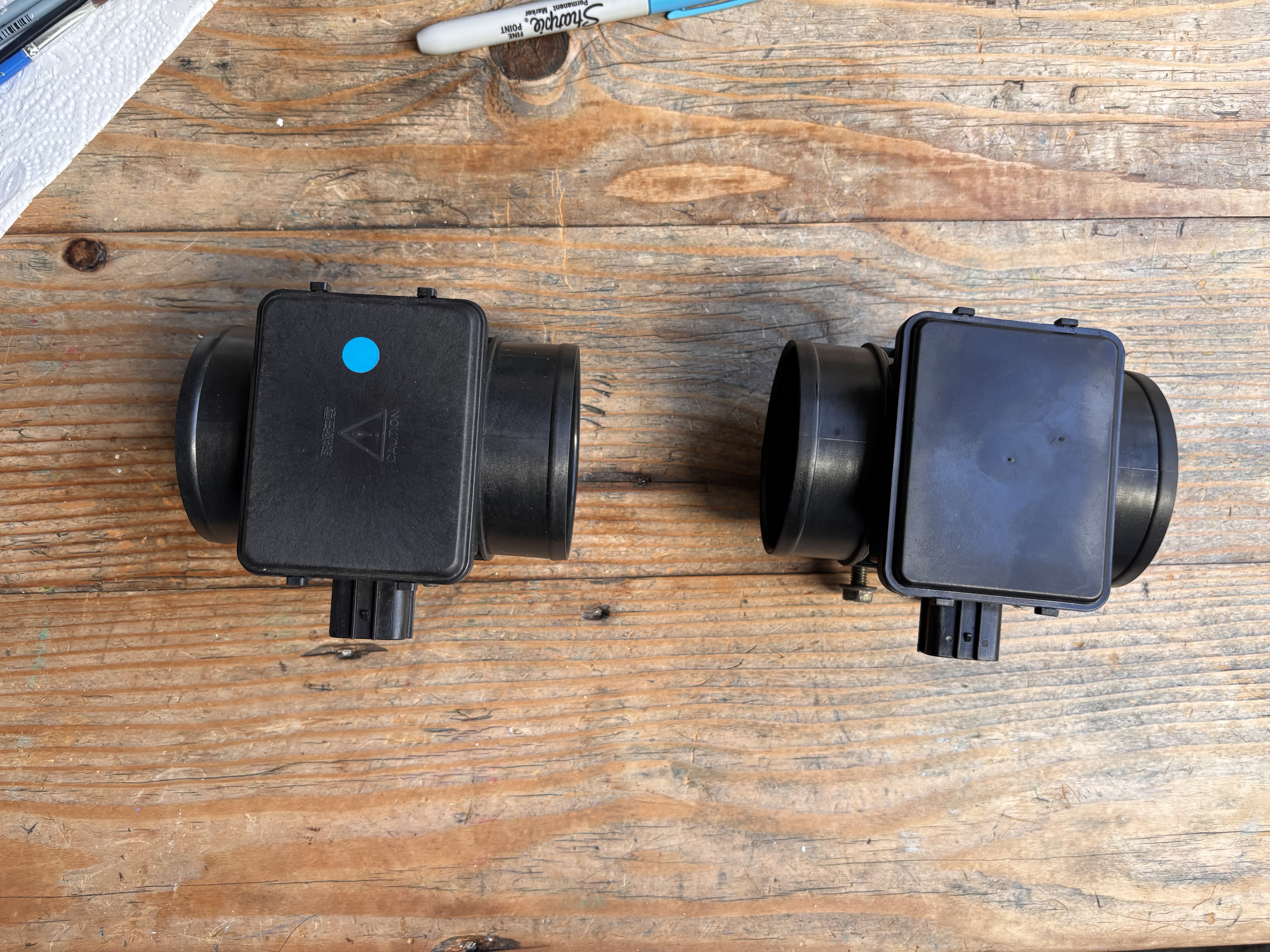
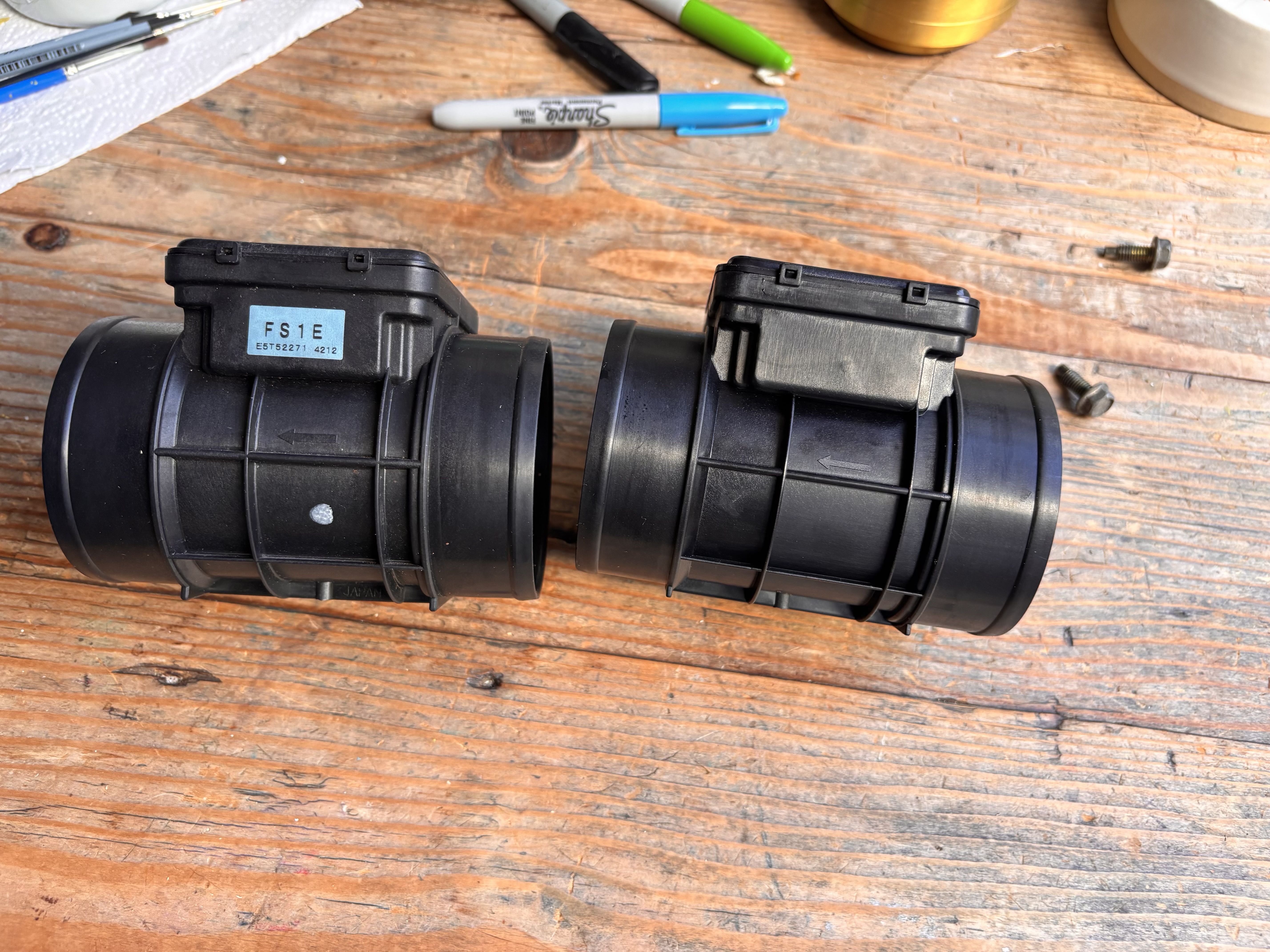
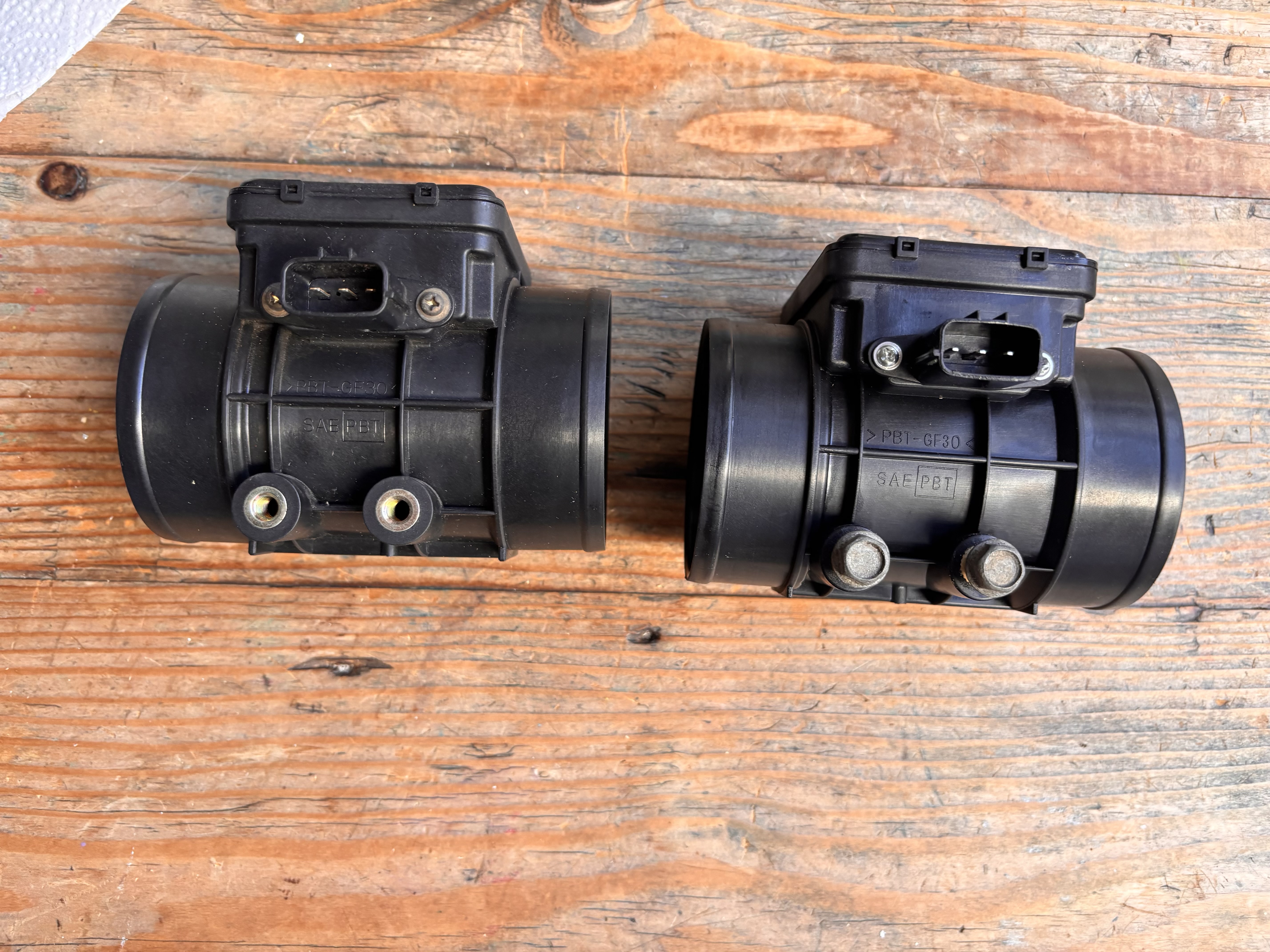
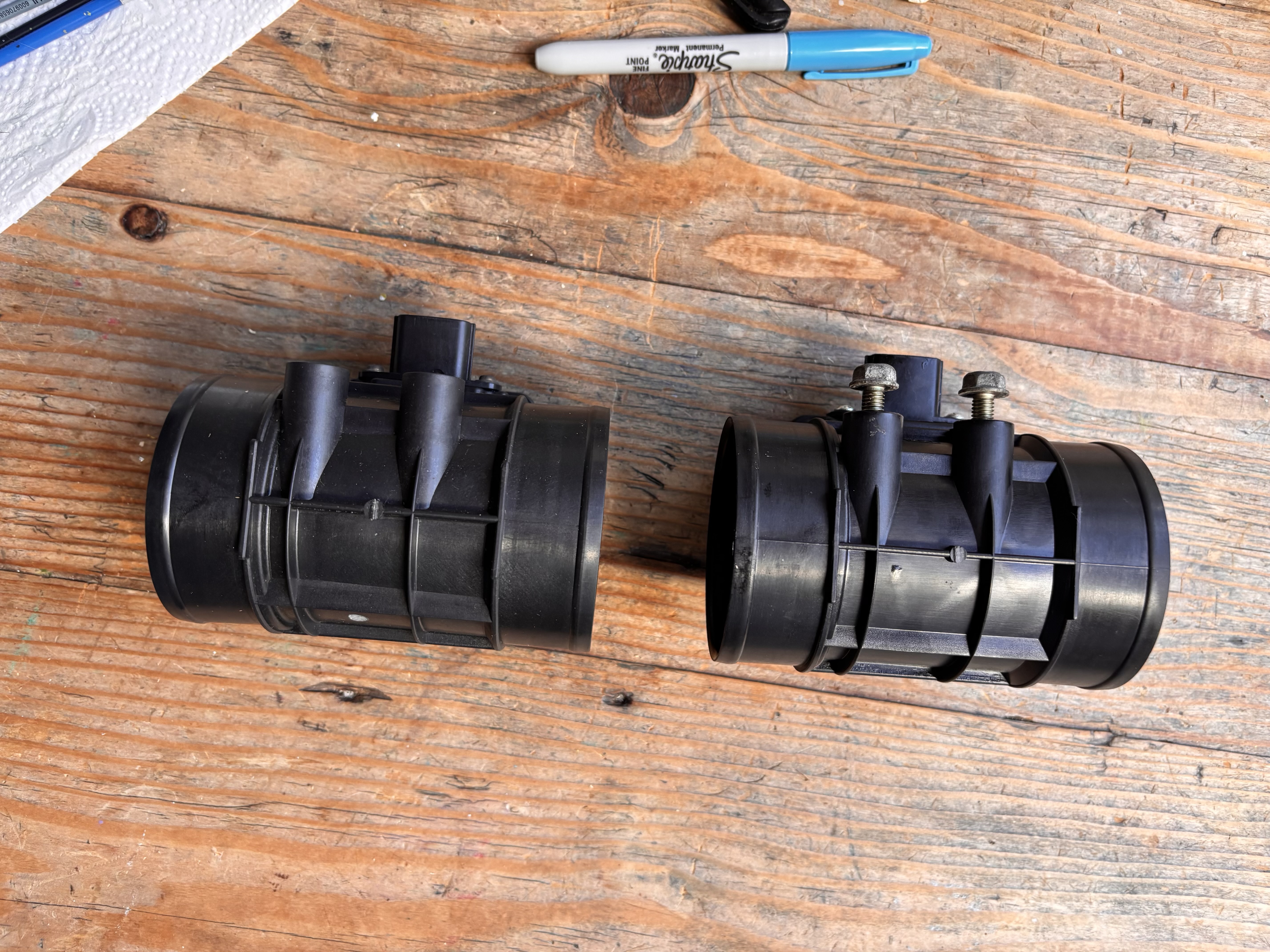
The moulding is close to identical, up to the text markings indicating the material used - Polybutylene Terephthalate with 30% glass filling. The clone, most likely made in China, is missing the “JAPAN” text.
And the sensing elements themselves — the OEM unit alongside two different aftermarket clones. Taken with an endoscope:
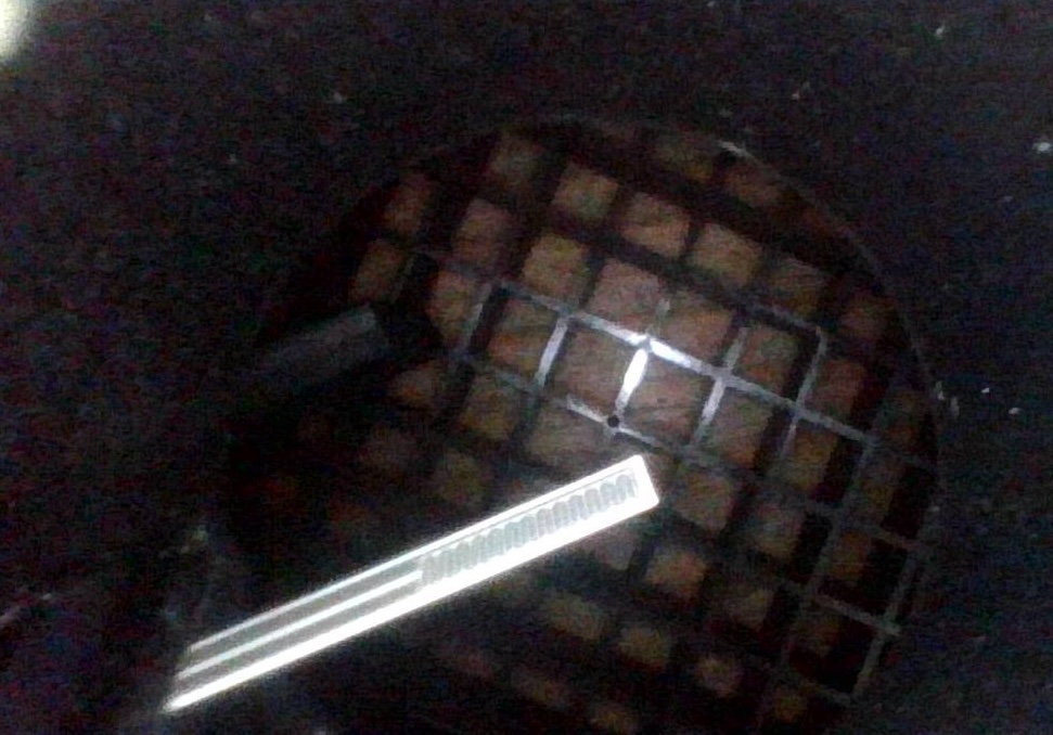
Not what I expected! Certainly does not look like the images of literal (hot)wire MAFs, or the newer membrane/MEMS style that you see online. The hotwire seems to be more like traces on a ceramic-like structure. This likely incorporates a platinum precision resistor.
The clones are of fairly different designs - one might expect less platinum:
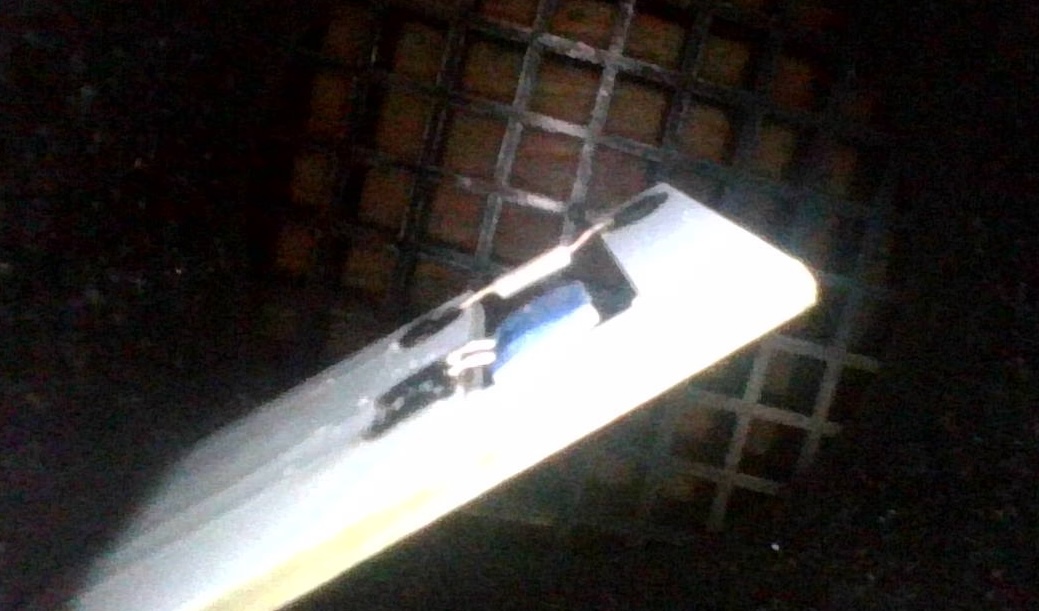
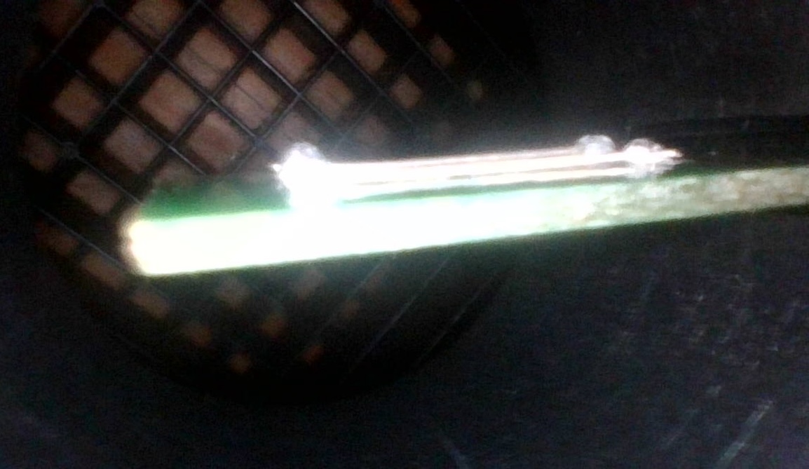
I wonder, to what degree, it’s possible to calibrate the aftermarket parts to match the OEM one more closely. One could take measurements by using a well controlled fan to produce airflow, and alter the output curve using an MCU with an ADC, DAC, and a suitable lookup curve. The car people would call this a signal conditioner?